Diagnostics
Wieland Electric GmbH | BA000966 | 07/2016 (Rev. C)
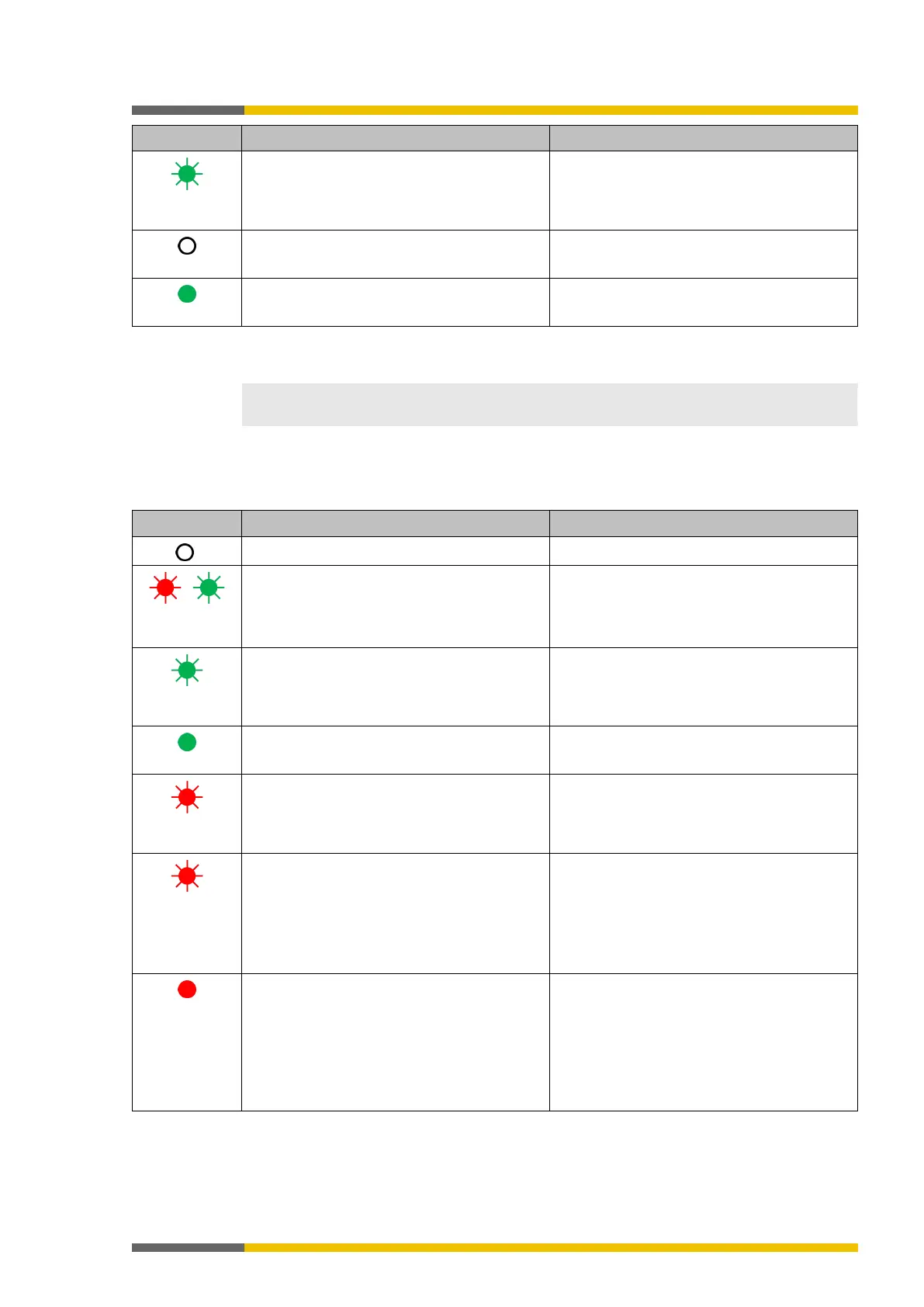
Green flashing
(1 Hz)
Output has a test error. Applies to Q1..Q4 and IQ1..IQ4
Output is switched off.
Output is switched off.
Device state and LED displays in the expansion modules (SP-SDIO, SP-SDI)
958954379
The displays of the MS LED and the input LEDs I1 to I8 are identical to those for the SP-SDIO
and SP-SDI expansion modules.
Device state and LED displays of the expansion module (SP-DIO)
1126481931
Table 39: Displays of the MS LED
Supply voltage outside of operating range Check supply voltage at terminals A1 and A2.
/
Red flashing
Repairable external error Check cable of flashing inputs and outputs.
If all output LEDs are flashing, check the
supply voltage of terminal A1 and A2 for this
module.
Green flashing
System in the stop state and waits for start
command or the voltage supply to A1 / A2 is
outside the range of 16.8V to 30V.
Start the application in samosPLAN5+.
Check voltage supply to A1.
System in the run state and the voltage supp-
ly to A1 is within the range of 16.8V to 30V.
Red flashing
Invalid configuration
Red flashing
(2 Hz)
Critical error (type 3) in the system; suspected
in this module. Application has been stopped.
Switch supply voltage off and back on.
If the error has not been eliminated after this
has been done multiple times, then replace
module.
In order to contain the module affected, use
the diagnostics display in samosPLAN5+.
Red
Critical error in the system; suspected in a
different module. Application has been stop-
ped.
Switch supply voltage off and back on.
If the error has not been eliminated after this
has been done multiple times, then replace
module in which the red LED is flashing (2
Hz).
In order to contain the module affected, use
the diagnostics display in samosPLAN5+.