Diagnostics
Wieland Electric GmbH | BA000966 | 07/2016 (Rev. C)
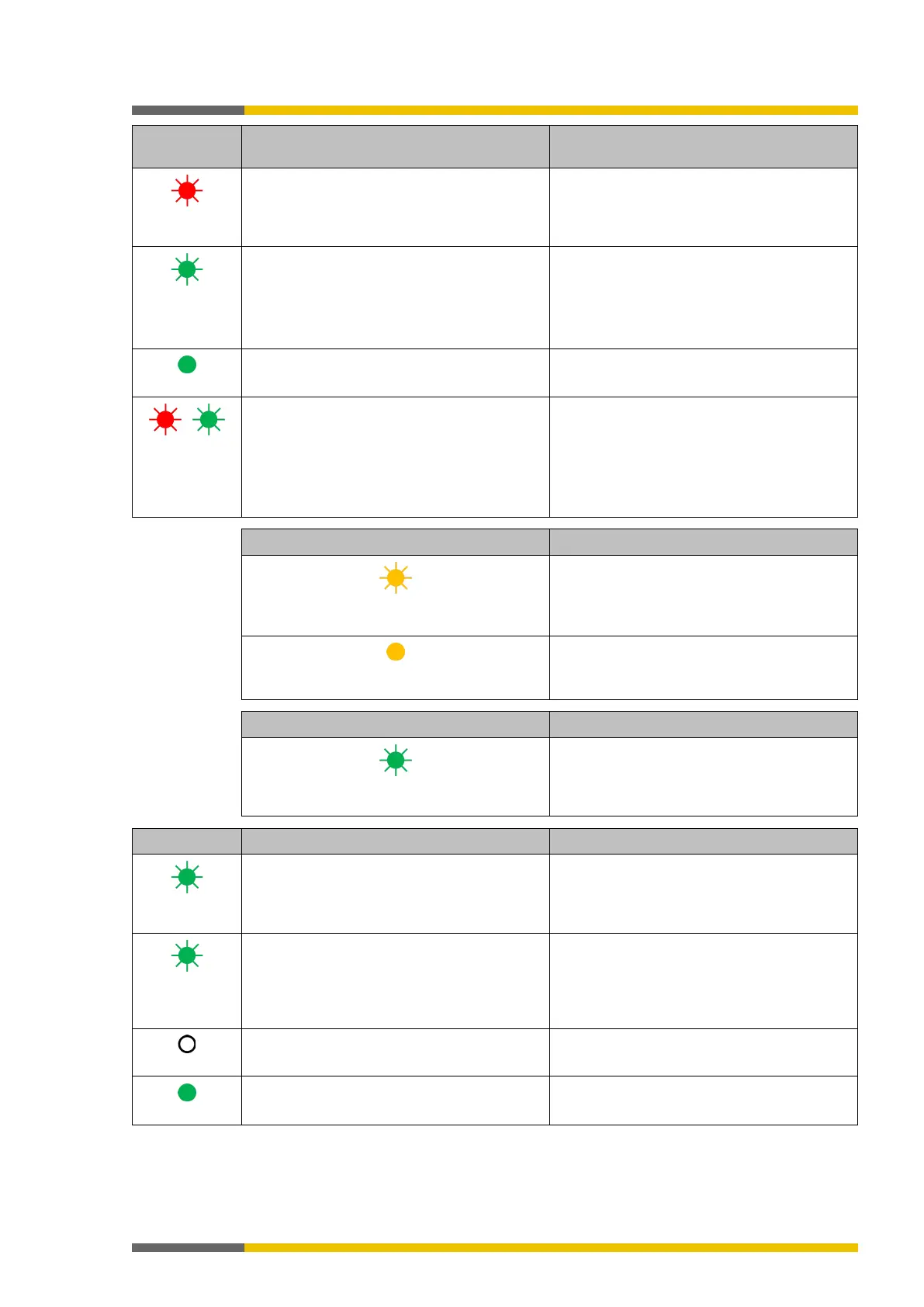
Red flashing (1
There is no project at the control or the pro-
ject data is faulty (because, e.g., the number
of inserted I/O modules does not match the
project)
No module or faulty module configuration
Green flashing
(1 Hz)
Project data adopted from control and I/O
modules; waiting for start command
Control has started.
/
Red/green
flashing
One or more inputs have a cable break or
short-circuit to 24V.
Or there is a sequence/synchronous time
error at a two-channel input.
Or an output has a test error (e.g. short-
Yellow flashing (1 Hz)
The project at the control has not been verifi-
ed.
The control will not start automatically after
Yellow
The project at the control has been verified.
The control will start automatically after
Flashing green
Connection setup with control
Green flashing
A single-channel input has a test error (cable
break or short-
circuit at 24 V) or the input was
not configured in the project and 24 V is pen-
ding.
Applies to I1 to I16 and IQ1 to IQ4 if single-
channel has been configured.
Flashes synchronously with MS LED in red.
Green flashing,
alternating (1
Two-channel input has synchronous time
error or a sequencing error or at least one of
the two inputs has a test error (cable break or
short-circuit at 24 V)
Applies to I1 to I16 and IQ1 to IQ4 if two-
channel has been configured.
Input pair flashing on and off
Signal level at the input terminal is 0 V.
Signal level at the input terminal is 24V.