Connecting devices
Wieland Electric GmbH | BA000966 | 07/2016 (Rev. C)
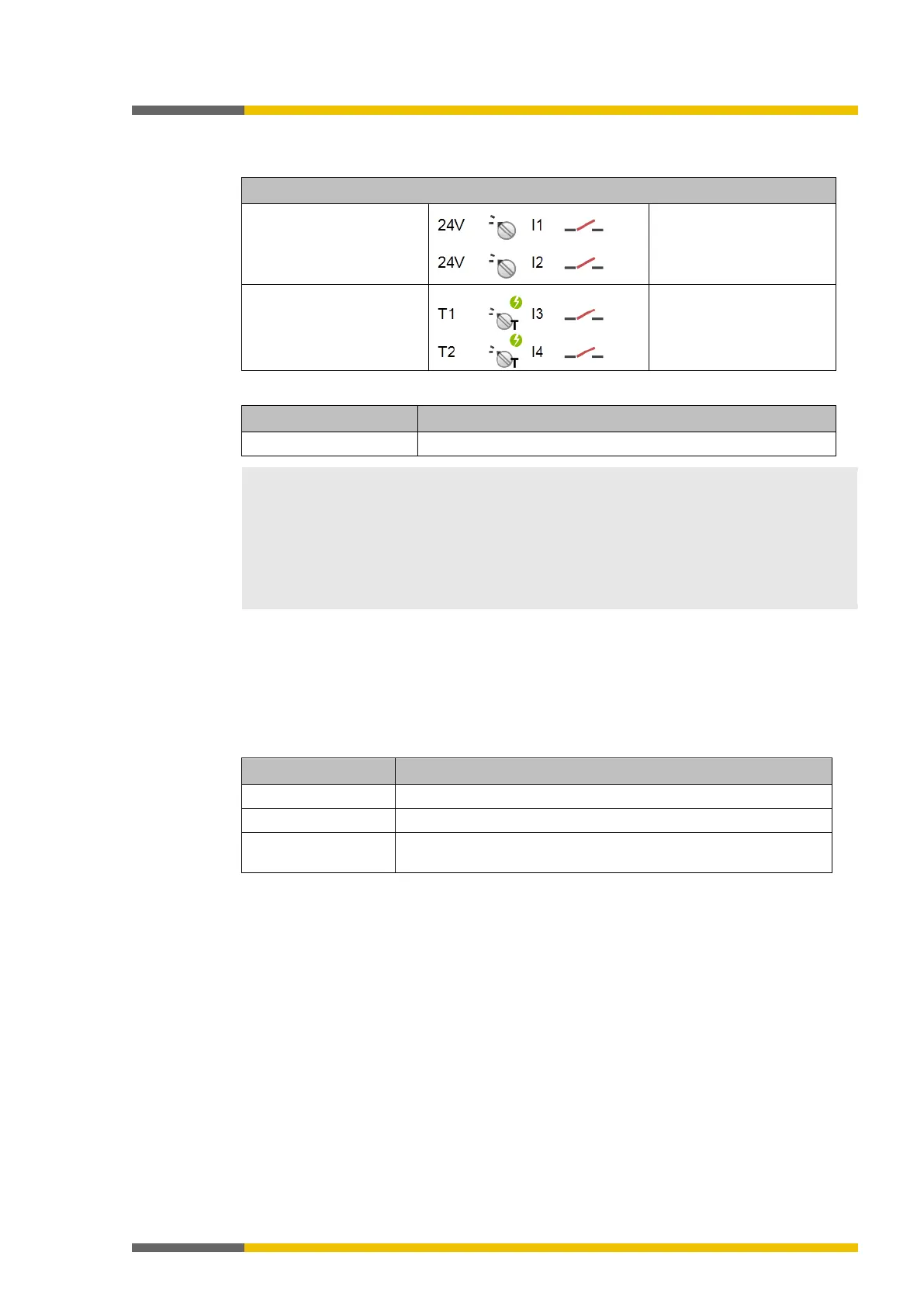
Mode selection switch
888464651
Electrical connection: Example from samosPLAN5+
Operating mode selection
switch (1 from 2)
to 24 V
Channel 1: Contact
between 24 V and I1
Channel 2: Contact
Operating mode selection
switch (1 from 2)
to test
output
Channel 1: Contact
between T1 and I3
Channel 2: Contact
between T2 and I4
• Operating mode selection switches without test pulses enable 2 to 8 operating modes;
operating mode selection switches with test pulses enable 2 to 4 operating modes.
• When wiring the tested operating mode selection switches, note that when using an odd-
numbered test output (X1, X3, X5, X7), odd-numbered inputs (I1, I3, I5, I7) must be used;
when using an even-numbered test output (X2, X4, X6, X8), even-
I6, I8) must also be used.
• You can find additional information in the operating instructions for the operating mode
Potential-free contacts
888469003
The samosPLAN5+ software provides a series of potential-free contacts for "free" designing of
contact elements. In this manner, you can implement different NO (normally open contact)/NC
(normally closed contact) combinations with and without testing. In addition, there are ele-
ments for a start and stop button, reset button, and device monitoring (EDM).
Table 25: Function of potential-free contacts
Series connection Possible
Discrepancy time Further information: "samosPLAN5+ Software" manual