Technical data
Wieland Electric GmbH | BA000966 | 07/2016 (Rev. C)
Test periods for both test outputs (ms)
1
800 1000 800 ms
1
Obtain the values from the report in samosPLAN5+.
Example
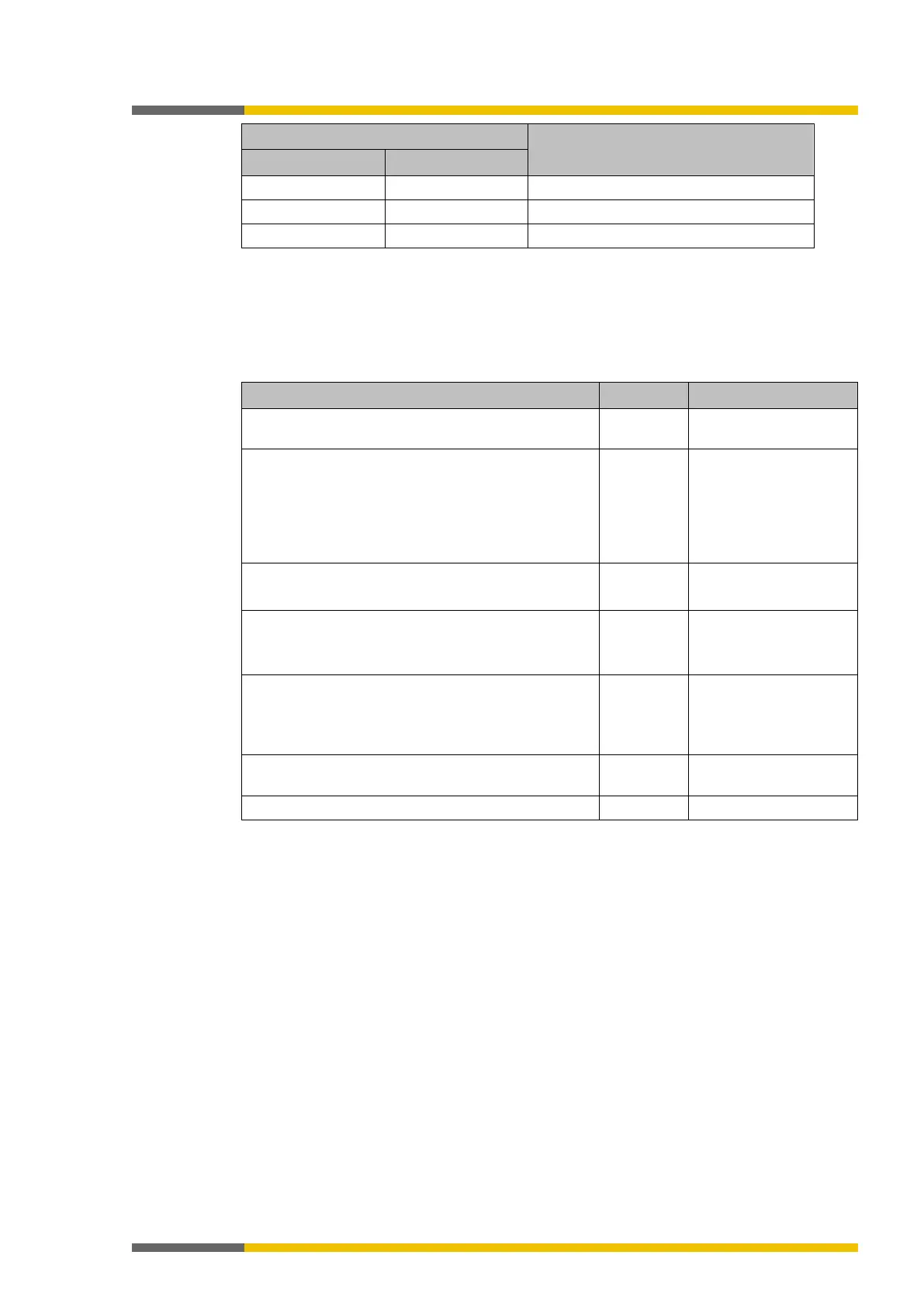
The following examples shows the determination of the response time of a safety function
(sensor – logical function – actuator).
Table 44: Response time of a safety function
Response time of the sensor + 18.0 ms Manufacturer informati-
for testable sensors, e.g. type 2 contactless
safety devices
With testable sensors, the response time increases by
the active test gap + 12 ms.
Thus, with a test gap of 4 ms, there is an additional
response time of 4 ms + 12 ms = 16 ms
+ 16.0 ms Test generators T1 to T4
or X1 to X8
When the ON-OFF filter is active, + 8 ms
0.0 ms samosPLAN5+
Compact input to Compact output
With a cycle time of 4 ms.
+ 11.6 ms See table: "Standard
time"
Logics for switch-off delay times
If function blocks with switch-off delay are used in
the logic plan, then these times have to be added to
0.0 ms samosPLAN5+
Actuator response time + 35.0 ms Manufacturer informati-
Minimum switch-off time
888557707
The minimum switch-off time (e.g. of connected sensors) is the minimum time during which a
switch-off condition must be present in order to be detected so that error-free switching is
possible. The minimum switch-off time must be
• greater than the logic execution time and
• greater than the test gap + the maximum OFF/ON delay when the input is connected at
test output X1–X8 and the test gap is > 1 ms, and
• greater than the test period + the maximum OFF/ON delay when safety mats or safety ed-
ges are being used.
Response time of the state flag
1126546187
If an error is detected, the state data will be available in the logic editor in the next logic cycle.
The time to detection of a state error depends, among other things, on the duration of the test
period and can be up to 1 s.