Connecting devices
Wieland Electric GmbH | BA000966 | 07/2016 (Rev. C)
ESPE – Electro-sensitive protective equipment
888500491
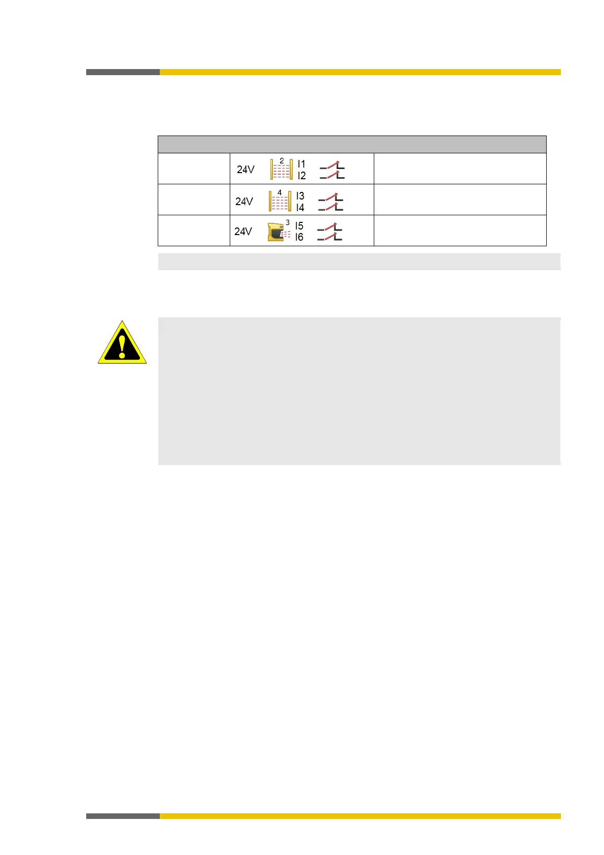
Table 36: ESPE connection
Electrical connection: Example from samosPLAN5+
SLC-2
OSSD1 (receiver) at I1
SLC-4,
OSSD1 (receiver) at I3
Laser scanner
ESPE type 3
OSSD1 (receiver) at I5
You can find additional information in the operating instructions for the respective ESPE.
Safety outputs
888506507
ATTENTION
Safety-based devices must be suitable for safety-relevant signals!
An interruption in the function of safety outputs will lead to a loss of safety functions, which
means that there will be a risk of severe injury.
• Do not connect any loads that exceed the rated values of the safety outputs.
• Wire the samosPRO system such that no 24 V DC signals can unintentionally make
contact with the safety outputs.
• Connect the GND lines of the power supply to ground so that the devices do not switch
on when the safety output line is at ground potential.
• Use suitable components or devices that fulfill the applicable guidelines and standards.
• Actuators can be wired at the output as single-channel. To ensure that the corresponding
safety integrity levels can be adhered to, the lines must be routed such that short-circuits
to other signals can be prevented, e.g. by routing them within protected areas such as
switchboxes or in separate shielded cables.