Technical data
Wieland Electric GmbH | BA000966 | 07/2016 (Rev. C)
Technical data
888548747
samosPRO system response times
888550283
The response time is the time that is required to activate the safety function.
Example: The time from which the safety light barrier is crossed until the machine stops.
In order to determine the response time of the samosPRO system, use the standard time plus
the filter and test times.
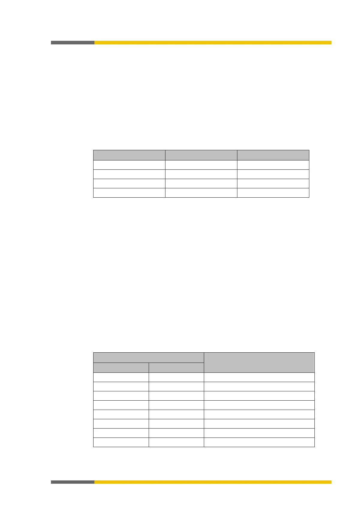
Maximum ON-OFF time from input to output without filter and test times:
Table 42: Calculating the time values
• The cycle time must be obtained from samosPLAN5+ (lower right).
• FSO = Fast Shut-Off: This function can be used to achieve quicker switch-off times from
input to output inside the module. FSO is a functional component in samosPLAN5+.
When the ON-OFF filter is activated, the switch-off signal is delayed by the filter time set. This
filter can be activated for each input in the samosPLAN5+ and acts upon the response time
with + 8 ms.
If the input tests are carried out in single-channel input circuits with the assistance of tests
outputs T1 to T4 or X1 to X8, this results in the response time for test times > 1 ms from the
test time plus 12 ms (wait time until the test pulse occurs).
When using user-defined elements (SW manual 5.4.5) the response time can also be extended
in two-channel input circuits if the selected test time is greater than 0.5 * test period minus
12 ms. The resulting additional response time should be calculated as follows:
additional response time = test time + 12ms - 0.5 * test period
(Only a positive result is evaluated, negative values are equal to zero)
For applications with a safety mat, the test period of the test generators connected must be
applied to the response time. The following table provides the reaction times for the corres-
pondingly set test periods.
Table 43: Test periods and response times
Test periods for both test outputs (ms)
1