Connecting devices
Wieland Electric GmbH | BA000966 | 07/2016 (Rev. C)
Testable single-beam safety light barriers
888486027
Testable type 2 single-beam safety light barriers
888487563
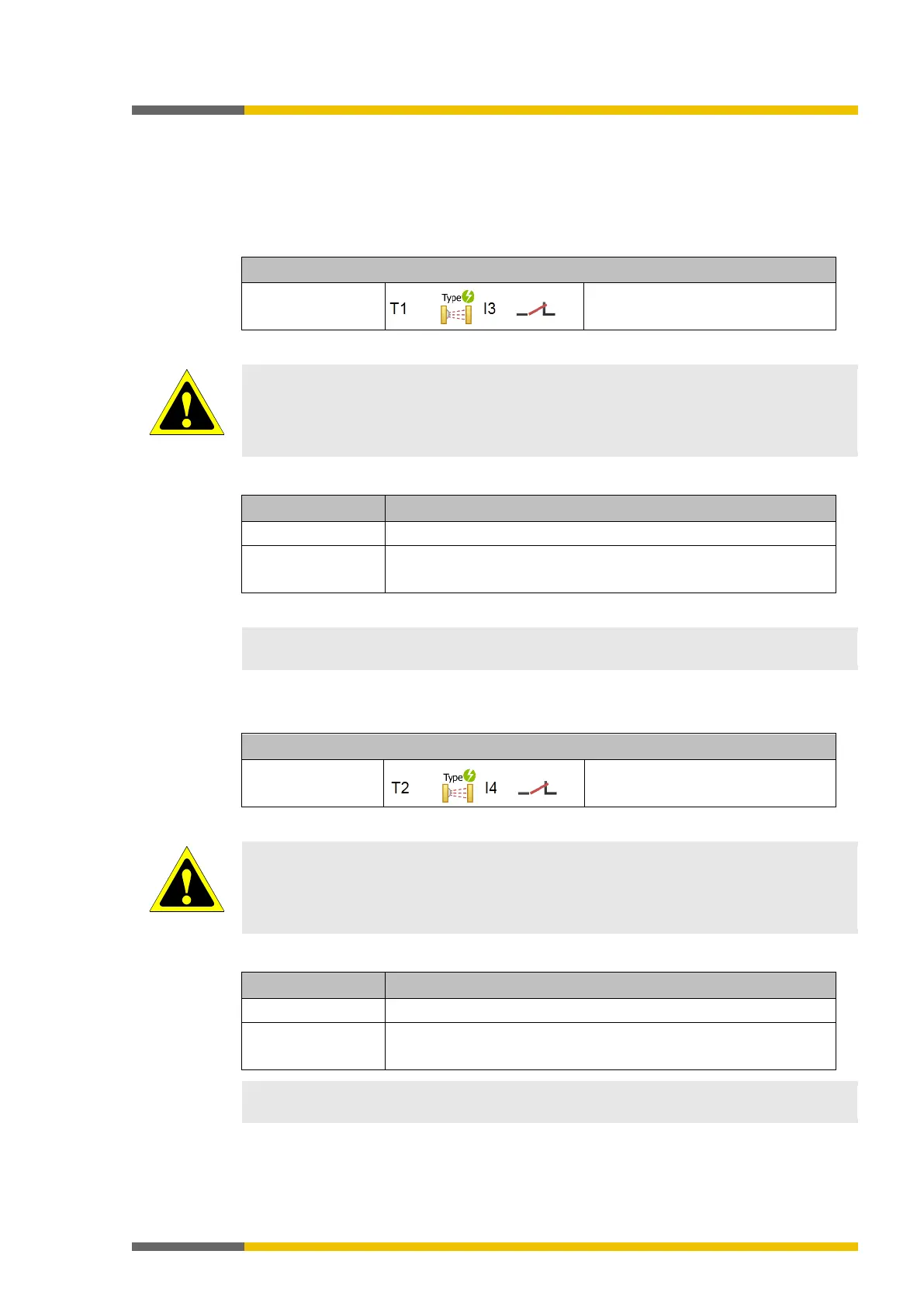
Table 33: Connecting testable type 2 single-beam safety light barriers
Electrical connection: Example from samosPLAN5+
SLB type 2
Test input TE (transmitter) at T1
Output Q (receiver) at I3
Note the safety information and protective measures!
Route the transmitter and receiver lines outside of the switchbox so that a short-circuit
between these lines can be avoided, e.g. route them separately in separate sheathed cables
or protected areas.
Table 34: Functions with testable type 2 single-beam safety light barriers
Series connec-
tion/cascading
Possible, depending on the safety light barrier type used
Note the maximum line resistance of 100 Ω.
You can find additional information in the operating instructions for the type 2 single-beam
safety light barriers.
Testable type 4 single-beam safety light barriers
888490251
Electrical connection: Example from samosPLAN5+
SLB type 4
Test input TE (transmitter) at T2
Output Q (receiver) at I4
Route the transmitter and receiver lines outside of the switchbox so that a short-circuit
between these lines can be avoided, e.g. route them separately in separate sheathed cables
or protected areas.
Table 35: Functions with testable type 4 single-beam safety light barriers
Testing Required
Series connec-
tion/cascading
Maximum of seven pairs per inputs
Note the maximum line resistance of 100 Ω.
You can find additional information in the operating instructions for the type 4 single-beam
safety light barriers.