Connecting devices
Wieland Electric GmbH | BA000966 | 07/2016 (Rev. C)
Customer-specific testable single-beam safety light barriers
888492939
You can find additional information on creating customer-specific elements here:
"samosPLAN5+ Software" manual (BA000968)
• Select the minimum value for the desired test gap in the settings of the customer-specific
element dialog.
• Regardless of the test gap, the entire OFF-ON delay of the cascade must be less than the
maximum OFF-ON delay of the respective test output (as shown in the report for the
samosPLAN5+) – 2 ms. Otherwise, the test gap will cause a switch-off. With SP-COP,
SP-SDIO, or SP-SDI modules, this value = 12 ms – 2 ms = 10 ms.
• Use a shielded or separate cable for the connections from the test output of the module
(X1 to X8) to the test input of the transmitter and from the output of the receiver to the
safe input of the module (I1 to I8). Otherwise, a short-circuit between the signals may
prevent error detection by this test.
Information on installing testable single-beam safety light barriers
888494475
Note the installation information in the operating instructions for the respective sensors
and particularly the following points:
• Single-beam safety light barriers may only be used as access protection in accordance
with EN ISO 13855. They may not be used as finger or hand protection.
• Maintain the minimum distance to reflective surfaces.
• The safety distance between the light beam and the danger point for the access protec-
tion must absolutely be adhered to.
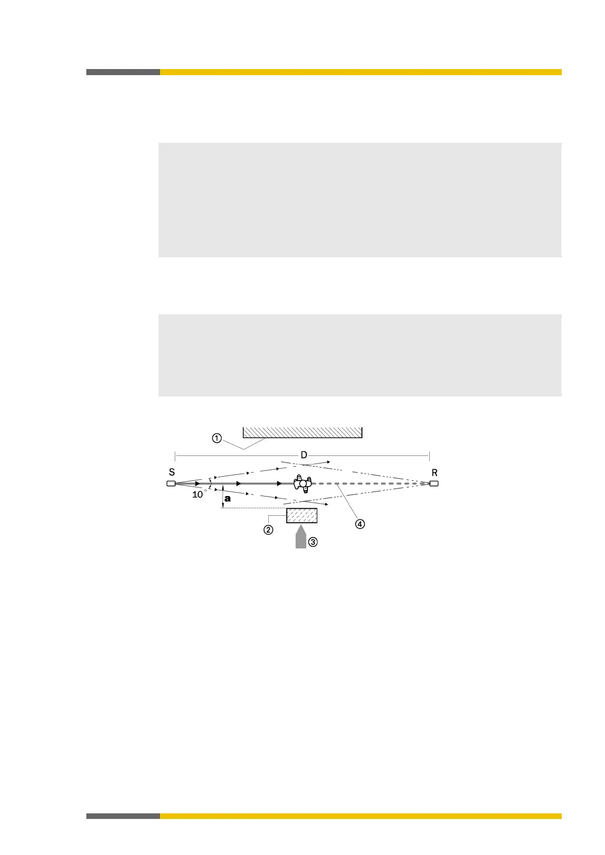
Illustration 21: Minimum distance "a" to reflective surfaces, correct installation, and alignment
S = transmitter R = receiver D = distance between transmitter and
1 = border to the hazardous area
2 = reflective surface
3 = entry direction to the hazardous area
4 = optical axis
a = minimum distance to reflective surface