Technical data
Wieland Electric GmbH | BA000966 | 07/2016 (Rev. C)
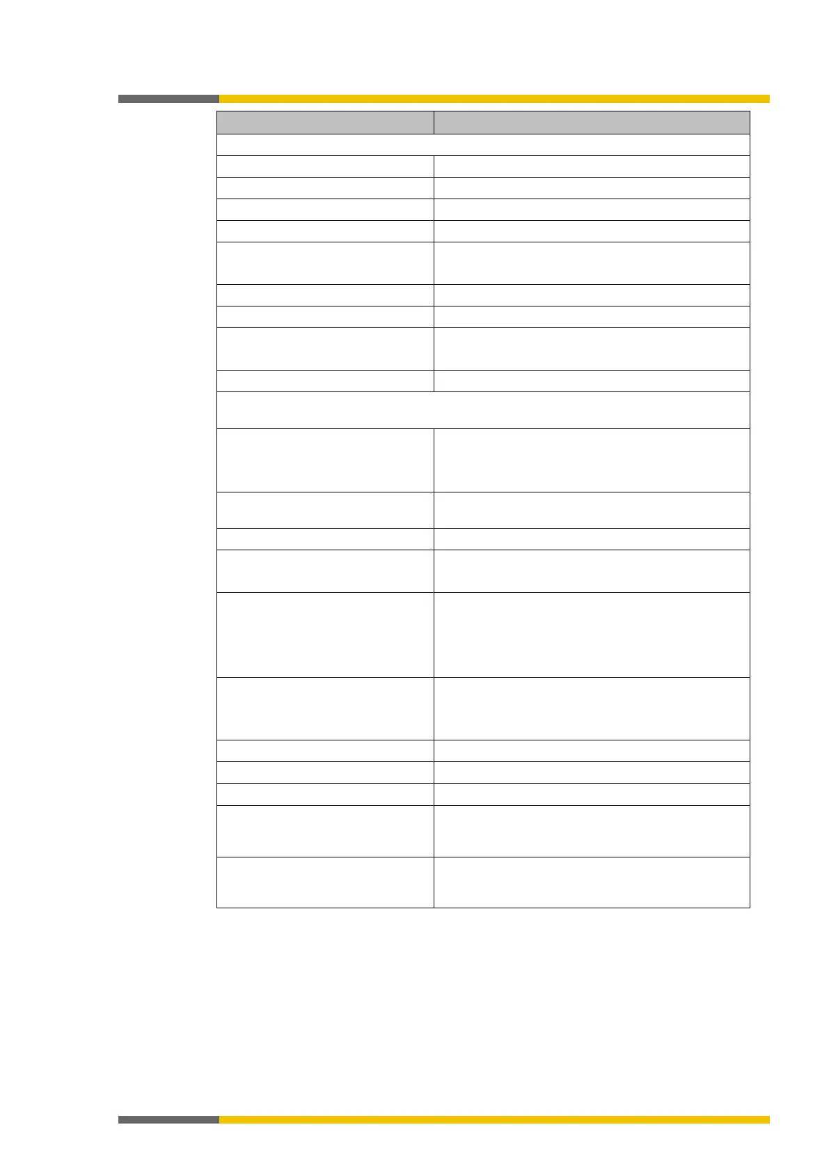
4 (with 4 test signal generators)
Semiconductor, push-pull, short-circuit-proof
Output current HIGH Single output: max. 120 mA
Total of all test outputs: max. 120 mA
Test pulse rate (test period)
Test pulse duration (test gap)
1 to 100 ms, configurable
Load capacity
1 µF for test gap ≥ 4 ms
0.22 µF for test gap 1 ms
Line resistance
Safety outputs
SP-COP1: Q1 to Q4 / SP-COP2-ENx: Q1 to Q4, IQ1 - IQ4
Number of outputs
• SP-COP1:
4
8 (4 fixed and 4 selectable outputs)
Type of output High-side MOSFET, short-circuit-proof and current-
Output current HIGH
Max. overload current/duration
≤ 4.0 A
Total current I
tot
T
U
≤ 45°C
T
U
≤ 55 °C
Per output pair (Q1/2, Q3/4, IQ1/2, IQ3/4)
≤ 4.0 A
≤ 2.5 A
Output test, can be deactivated
3,4,5
Test pulse width
≤ 450 µs
6
7
Maximum permissible coil energy
without external protection ele-
8
< 0.125 J
Response time Depends on logic setup
(Details:
samosPRO system response times [ch.
1
For detailed information regarding the safety configuration of your machine/system, please
contact the Wieland Electric branch in charge of your area.
2
Do not connect any other safe inputs in parallel when the reverse current could lead to a
HIGH state at the other input.
3
When activated; in that case, the outputs are tested regularly (brief LOW switching). When
selecting the downstream control elements, make sure that the test pulses will not cause
switch-off with the previously listed parameters or deactivate the test pulses at the outputs.