Technical data
Wieland Electric GmbH | BA000966 | 07/2016 (Rev. C)
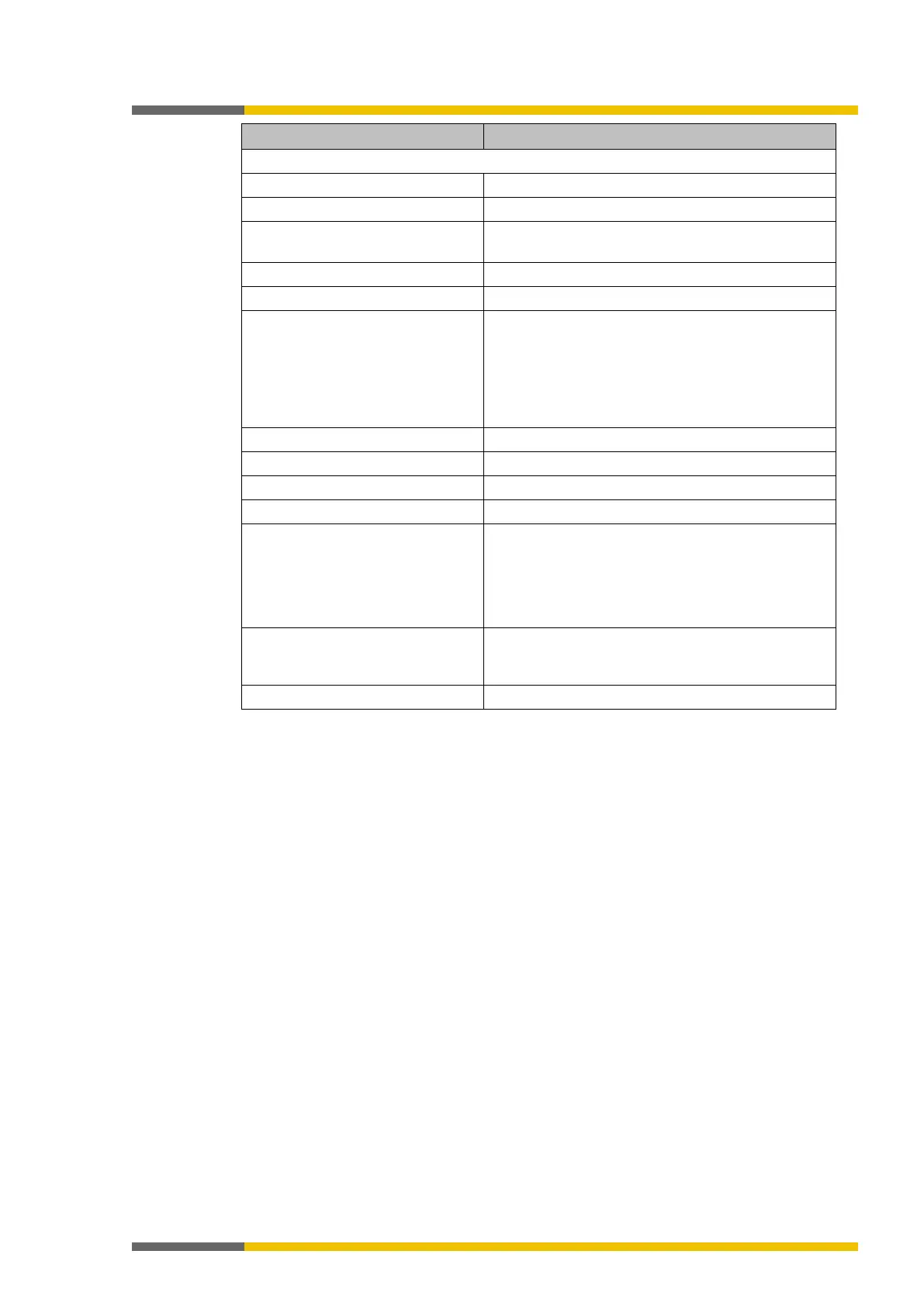
Safety outputs (Q1 to Q4)
High-side MOSFET, short-circuit-proof
Output voltage HIGH 16 to 30 V DC (max. 0.8 V drop to terminal A1 on
3
Total current I
tot
TU ≤ 45°C
TU ≤ 55 °C
TU ≤ 65°C
Max. 4.0 A
Max. 3.2 A
Max. 2.5 A
4
5,6
7
Max. 5 Ω (e.g. 100 m × 1.5 mm² = 1.2 Ω)
Maximum permissible coil energy
without external protection ele-
ments
8
Hardware version V1.00
0.22 J
0.37 J
Response time Depends on logic setup
(Details:
samosPRO system response times [ch.
1
When safety outputs are being used without test pulses, then either all of the safety outputs
without test pulses must be switched off at least once a year simultaneously for at least one
second or the samosPRO system must be restarted by switching off the supply voltage.
2
Do not connect any other safe inputs in parallel when the reverse current could lead to a
HIGH state at the other input.
3
In the event of a fault (interruption in the 0 V line), the maximum of the leakage current will
flow in the OSSD line. The downstream control element must determine this state as being
LOW. An FPLC (Failsafe Programmable Logic Controller) must be able to detect this state.
4
When activated; in that case, the outputs are tested regularly (brief LOW switching). When
selecting the downstream control elements, make sure that the test pulses will not cause
switch-off with the previously listed parameters or deactivate the test pulses at the outputs.
5
When safety outputs are being used without test pulses, then either all of the safety outputs
without test pulses must be switched off at least once a year simultaneously for at least one
second or the samosPRO system must be restarted by switching off the supply voltage.
6
If safety outputs are being used without test pulses:
Use shielded or separate cabling for safety outputs the test pulses of which have been deacti-
vated, because a short-circuit to 24 V will not be immediately detected if the output is HIGH. In
the event of a detected internal hardware error, this could affect the ability to switch off the
other outputs through reverse current.
7
Limit the line resistance of the individual lines to the downstream control element to this va-
lue in order to ensure that a short-circuit will be reliably detected between the outputs. (Also
see EN 60204, Safety of machinery - Electrical equipment of machines - Part 1: General requi-
rements.)
8
Examples of the resulting maximum coil induction:
HW V1.00: 1760 mH @ 0.5 A, 440 mH @ 1 A, 110 mH @ 2 A
HW V1.01: 2960 mH @ 0.5 A, 740 mH @ 1 A, 185 mH @ 2 A
 Loading...
