Technical data
Wieland Electric GmbH | BA000966 | 07/2016 (Rev. C)
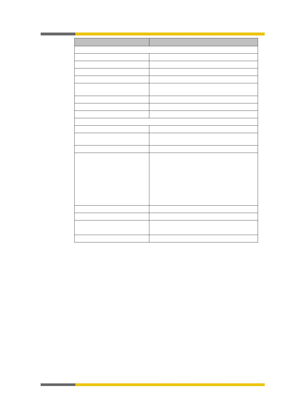
Input reverse current with ground
breakdown
2
Max. 20 mA
1.5 k
effective reverse resistance for supply current
4 ms to 30 ms, configurable
8 (with two test signal generators)
Type of output PNP semi-conductor, short-circuit-proof, cross-
Output current Max. 120 mA at both of the two test signal genera-
tors (X1/X3/X5/X7 or X2/X4/X6/X8)
Thus, a maximum of eight testable sensor cascades
are possible per module with a maximum of 30 mA
each.
The total current of the samosPRO system is limited
to a maximum of 1.28 A. This corresponds, for exa-
mple, to 32 inputs of testable sensors with 30 mA
and 64 inputs of SP-SDIO or SP-SDI modules.
Test pulse rate (test period)
Test pulse duration (test gap) 1 to 100 ms, configurable
Load capacity
1 µF for test gap ≥ 4 ms
Line resistance
< 100
1
For detailed information regarding the safety configuration of your machine/system, please
contact the Wieland Electric branch in charge of your area.
2
Do not connect any other safe inputs in parallel when the reverse current could lead to a
HIGH state at the other input.