Manual 37365A GCP-30 Series Packages - Genset Control
© Woodward Page 131/179
Starting Sequence
If the control is equipped with a three-position frequency controller, a continuous "Frequency lower prior to
start" signal (time adjustable via Parameter 262) is output before starting the engine. The starter is enabled after
the tim
e configured in parameter 262 expires. The ignition is enabled following the expiration of the ignition de-
lay time (Parameter 256) and if the engine is rotating with at least the configured "minimum speed for ignit."
(Parameter 255). Following the expiration of the gas valve delay (Parameter 257), the gas valve is enabled. If the
st
arting sequence finishes successfully (the firing speed (Parameter 272) was exceeded) the starter is disengaged.
The gas valve and the ignition rem
ain enabled by means of the firing speed. After reaching the "f-controller:
starting frequency" (Parameter 39) and the delayed engi
ne monitoring has expired (Parameter 271), the speed
controller is enabled.
Stopping Sequence
When the start request is terminated, a power reduction is performed (if the real power controller is enabled,
Parameter 74). After the GCB has opened, an engi
ne cool down is performed (Parameter 270). When the engine
cool down period expires, the gas valve is closed, and the engine is stopped. When the engine speed falls below
the firing speed (Parameter 272), the engine starting sequence is disabl
ed for 10 seconds. If the engine fails to
stop after 30 seconds, an alarm message is issued and a F3 class alarm is initiated.
After the engine speed has fallen below the firing speed, the ignition will remain enabled for an additional
5 seconds so that any gas remaining in the cylinders is able to combust.
Safety Instructions To Control Gas Valves
In order to ensure a safe shutdown of the gas valves, a separate shutdown circuit must be utilized.
The following is recommended to prevent the gas valve from failing to close due to stuck relays.
Controlling gas valves with the GCP
The GCP relay manager from V4.1001 and on contains function 131 ("fuel valve ON"). This function exists in
the GCP so that a relay configured with this function behaves like the "Gas valve" relay.
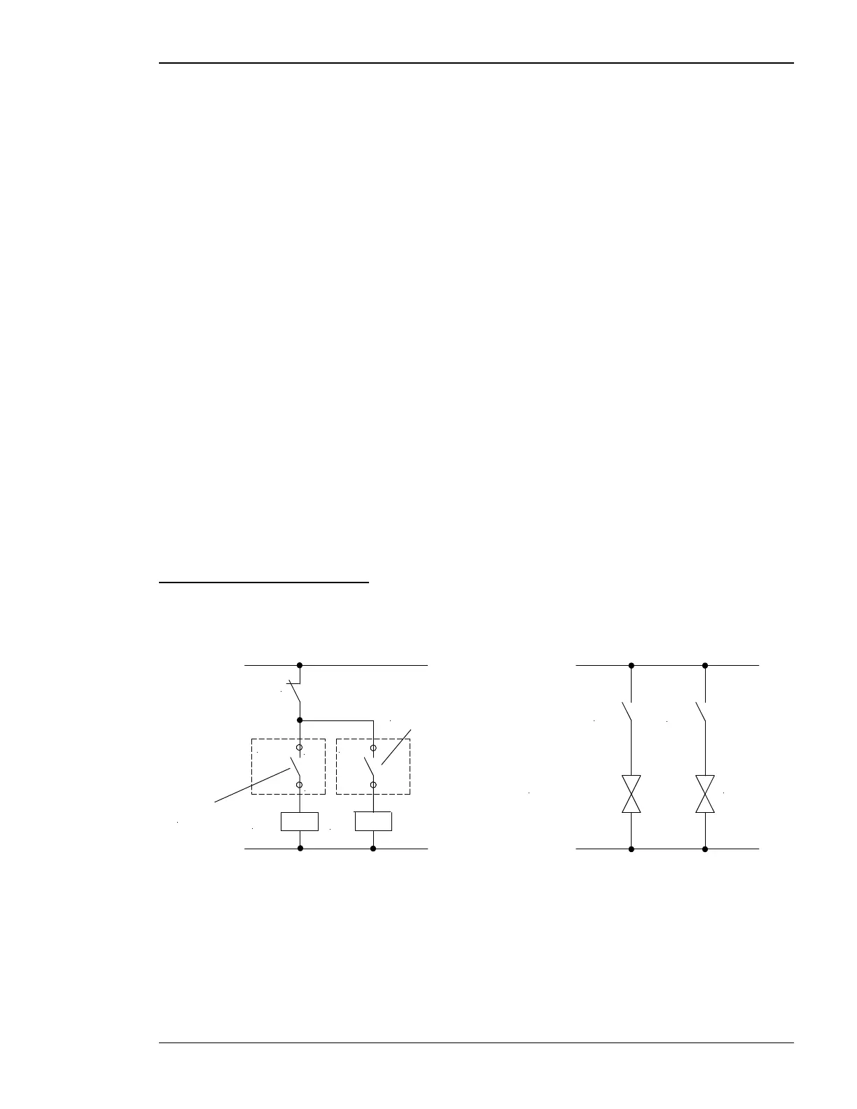
The wiring diagram shown below is an example of a recommended gas valve control system in the gas line.
Emergency
stop
K1
K2
GCP-30
Gas
valve
Relay
manager
param. 131
K1
K2
Gas valve 1 Gas valve 2
GCP-30
44
43
Figure 3-14: Wiring diagram for opening gas valves with the GCP-30 from V4.1001

 Loading...


