Manual 37365A GCP-30 Series Packages - Genset Control
Page 14/179 © Woodward
Chapter 3.
Configuration
Configuration may be performed via the front panel keys or using a PC and the LeoPC1 program via the serial
interface. LeoPC1 version 3.1 or higher is required to perform this. Configuration via a CAN bus converter is al-
so possible. The following communication protocols require the following baud rates:
• Direct configuration (RS-232) = 9,600 Baud (8 Bit, no parity, 1 Stop bit)
• CAN bus (CiA) (RS-485) = 125 kBaud
CAUTION
A PC with configuration software with the following revision number or higher is required to configure
this control (applies to firmware versions 4.3xxx or higher):
LeoPC1 from 3.1
GCP controllers with Option SC10 cannot be completely configured through the face panel. Therefore,
it is recommended to have LeoPC1 and the correct configuration files available when commissioning.
Due to functional enhancements of the GCP-30 control series, it is necessary (beginning with firmware version
4.3xxx) to use a newer version of the configuration software LeoPC1. This requires that LeoPC1 version 3.1 or
higher be used. If your current LeoPC1 software is an earlier version, the latest version can be ordered from our
technical sales or can be downloaded from our homepage at http://www.woodward.com/software.
Older project files may still be used with the updated version of LeoPC1 after installation has been completed.
These files should be transferred to the appropriate file locations within the updated version of LeoPC1.
WARNING
Please note that configuration only should be performed while the system is not operating.
NOTE
Prior to configuring a control unit, familiarize yourself with the parameters listed in this manual.
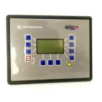
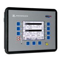
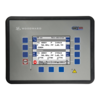
You can advance through the individual parameter screens if you are in configuration mode (simultaneously
pressing of "Digit↑" and "Cursor→" push buttons permits access to the configuration mode) by using the "Se-
lect" button. If you press and hold the "Select" push button, the scroll function will be activated, allowing for the
parameter screens to be advanced through more rapidly. The control unit will permit the operator to reverse up to
four previous screens (exception: it is not possible to reverse from the first parameter to the last parameter or to
backup through the service screens). To perform the reverse function through the parameter screens, the "Select"
and "Cursor→" push buttons must be pressed and released simultaneously. The control unit will revert to auto-
matic mode if an entry isn’t performed, a change made, or any other action performed for 90 seconds.
NOTE
Two hardware versions are described in this manual. The differences between these versions are 120
Vac and 480 Vac voltage-measuring inputs. Configuration screens and permissible limits of these units
will differ as well. These models are differentiated by numerals in the applicable text. The 120 Vac
model is identified by a [1] and the 480 Vac is identified by a [4] in front of the text that applies to the
unit.

 Loading...

