46 03/2016 – UM-MT-EN-01
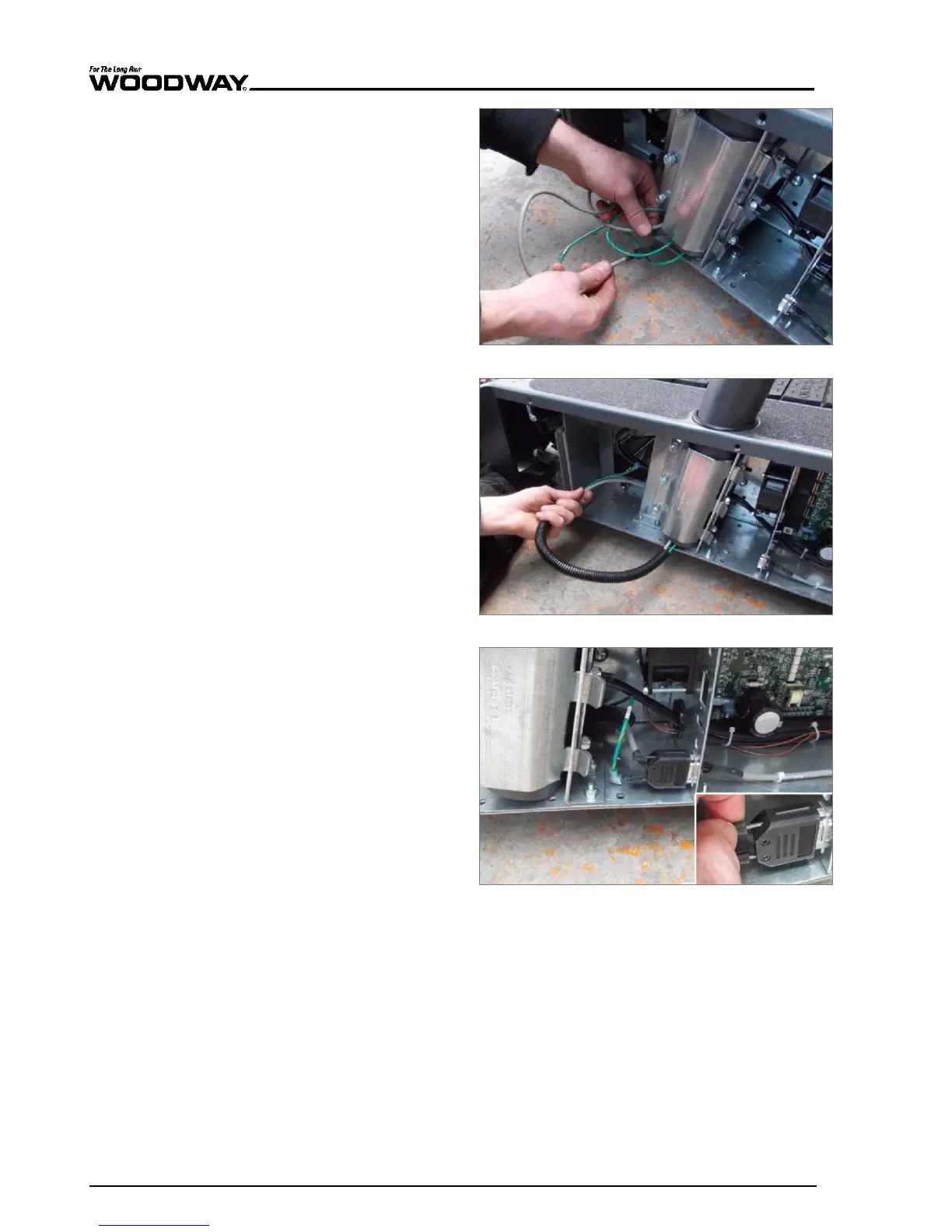
5. Pull the wire and protective
cover out of the handrail
tube.
Fig. 19 4Front assembly, connection 1
6. Lay the wire with protective
cover behind the handrail
mount.
Fig. 20 4Front assembly, connection 2
7. Insert the Display plug and
tighten both retaining
screws.
8. Attach the protective con-
ductor (green) to the con-
tact tab on the frame.
9. Connect any other connec-
tions to the interface panel
Fig. 21 4Front assembly, connection 3