58 03/2016 – UM-MT-EN-01
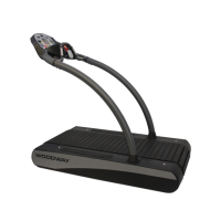
5. Tighten railing mount bolts
on the right side.
Fig. 54 Pro/Pro XL assembly, fixing the railing 1
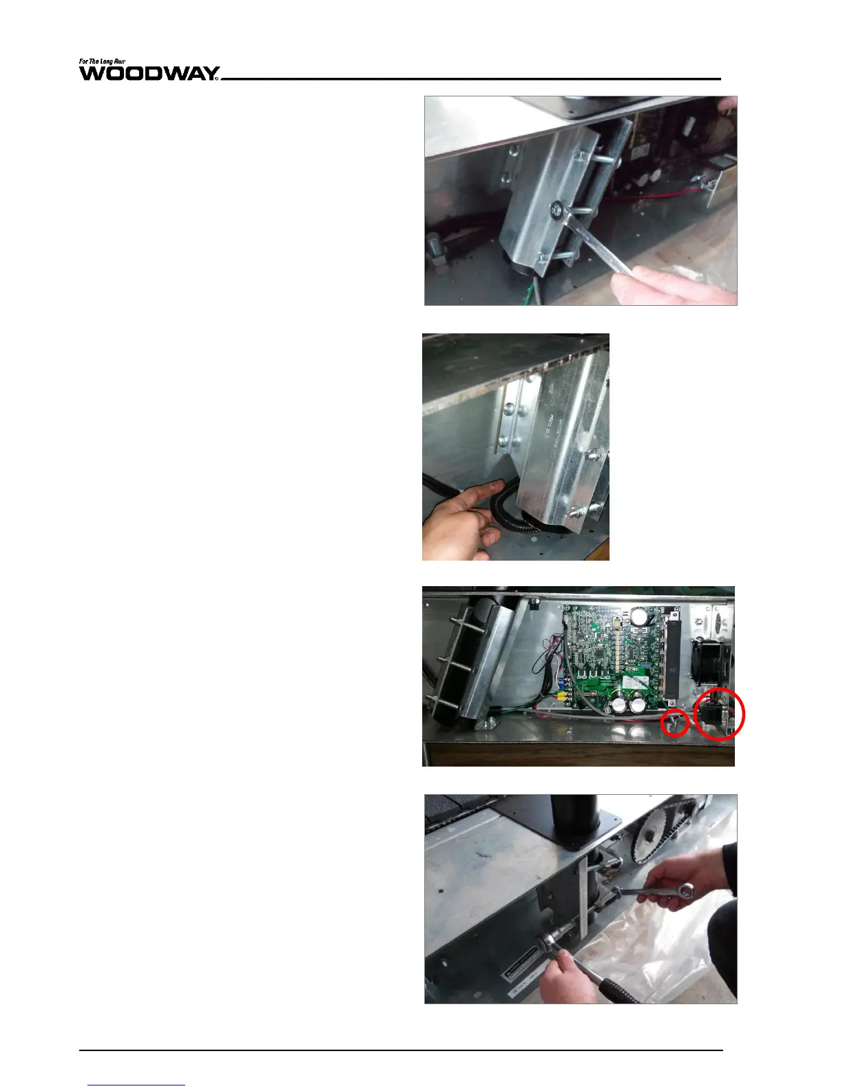
6. Pull the wire and wire pro-
tection out of the side of
the railing tube and lay it
along the railing mount to
the circuit board.
Fig. 55 Pro/Pro XL assembly, connection 1
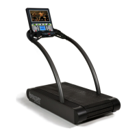
7. Insert the display plug and
tighten both retaining
screws.
8. Attach the protective con-
ductor (green) to the con-
tact tab on the frame.
9. Connect any other connec-
tions to the interface panel.
Fig. 56 Pro/Pro XL assembly, connection 2
10. Tighten railing mount bolts
on the left side.
Fig. 57 Pro/Pro XL assembly, fixing the railing 2