4 Parts Replacement RJ-901C/RJ-900C Maintenance Manual
4-56
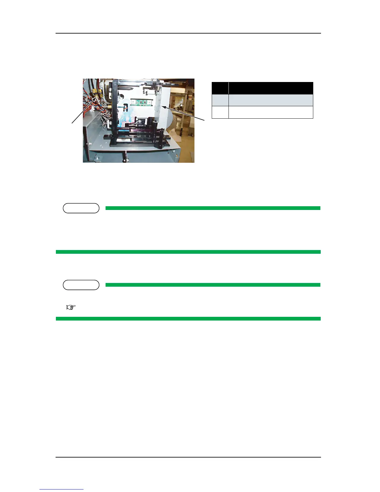
4. Remove the joint screw (M6) connecting the I/H assembly and the SUS pipe, and remove the o-ring
inside.
5. Remove the screw retaining the I/H assembly to the I/H base (tapping screw M3
× 10, S cup: 2pcs).
6. Replace the I/H assembly.
NOTE
The components of the different color I/H assembly are compatible each other except the following
parts.
• Incompatible parts: Ink sensor assembly
7. To reassemble the unit, reverse the removal procedure.
NOTE
When tighten the joint screw, use the optional jig and pay attention to the fastening torque.
"10.4 Jigs and Tools" p.10-7
No. Part name
1 Joint screw
2
I/H assembly
1
2