4 Parts Replacement RJ-901C/RJ-900C Maintenance Manual
4-64
6. To reassemble the unit, reverse the removal procedure.
4.10 Replacement of Cable Guide Section Components
4.10.1 Replacing CR Board Assembly
NOTE
Before replacing CR board assembly, remove the following covers.
•Top cover: "4.2.6 Removing Top Cover" p.4-13
• CR board cover: refer to the instructions up to step 4 in "4.6.1 Replacing Print Head" p.4-37.
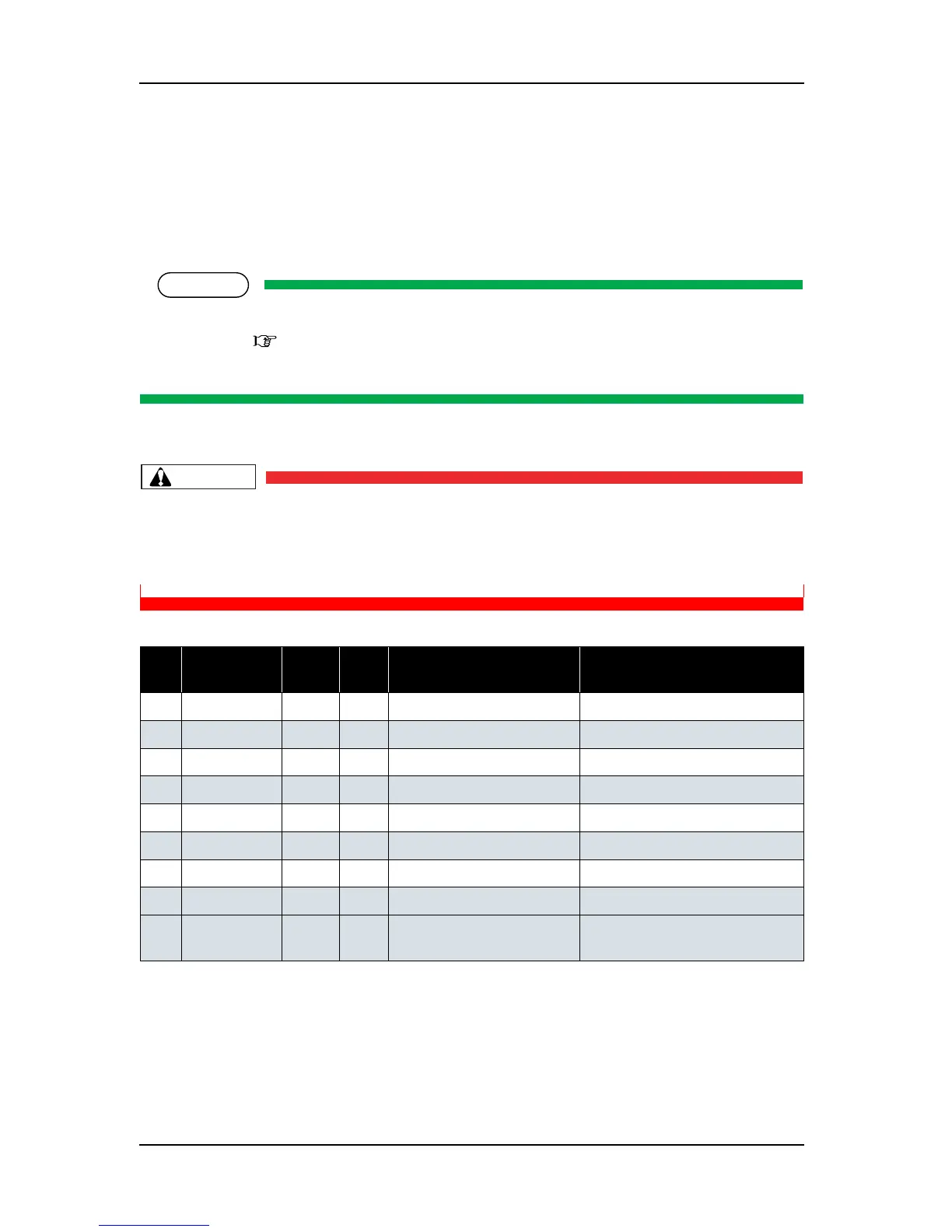
1. Remove the following connectors from the CR board assembly.
CAUTION
When connecting or removing the FFC type cables to the CR board assembly connector,
always pull or push the cables perpendicularly to the connector.
Pulling or pushing the wire slantwise may damage/short/break the terminals in the
connectors, resulting in a breakdown of the on-board elements.
Table 4-4 Connectors to CR Board Assembly
No. Connector
No.
# of
pins
Color Connect to Remarks
1J204
31 pins Black
Print head CN1
2 J205
31 pins Black
Print head CN2
3J201
31 pins Black
Main board assembly J11
4 J202
31 pins Black
Main board assembly J10
5J203
31 pins Black
Main board assembly J9
6 J207
4 pins White
CR_ENC assembly
7J206
2 pins White
Cutter solenoid assembly
8 J208
4 pins Black
P_EDGE sensor assembly
9 J209
3 pins White
PG origin point sensor
assembly