RJ-901C/RJ-900C Maintenance Manual 4 Parts Replacement
4-41
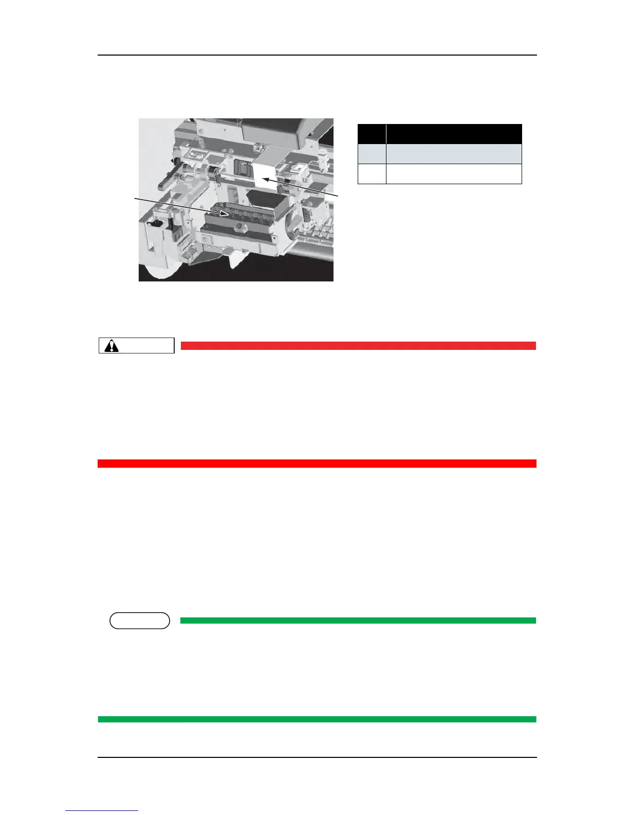
13. Remove the print head from the carriage.
14. Remove the two head tape wire from the print head.
CAUTION
• Do not touch the nozzles of the print head. Make sure that the nozzles do not get any dust.
• When connecting or removing the tape wire (FFC), always pull or push the wire
perpendicularly to the connector.Pulling or pushing the wire slantwise may damage/short/
break the terminals in the connectors, resulting in a breakdown of the print head.
• The folding orientation of the FFC (tape wire) differs between head side and the CR board
side.Make sure to attach the tape wire in the appropriate orientation.
15. Replace the print head.
16. To reassemble the unit, reverse the removal procedure.
17. Perform adjustments by following the instructions in "7.2 Adjustment Item" p.7-3.
4.6.2 Replacing Cutter Holder Assembly
(1) Replacing Cutter Holder Assembly
NOTE
Before replacing parts in the cutter holder assembly, remove the following parts referring to the
instructions shown below.
Removing the cable cover L, R: refer to "4.6.1 Replacing Print Head" p.4-37
Removing the P_EDGE sensor, cutter sensor connector: refer to "4.10.1 Replacing CR Board
Assembly" p.4-64
No. Part name
1 Print head
2
Head tape wire
1
2