4 Parts Replacement RJ-901C/RJ-900C Maintenance Manual
4-22
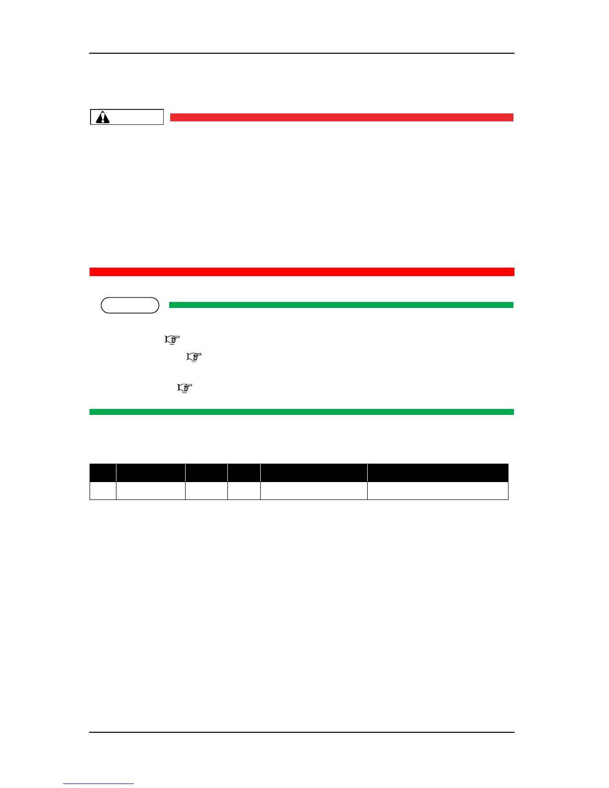
4.3.4 Replacing Power Board Assembly
CAUTION
• When removing the power board assembly, remove the power cable and wait for at least
5 minutes before taking it out; this will discharge the residual electrical charge of the
electrolytic capacitor.
If you handle these boards before the capacitor charge is fully discharged, you may suffer
electric shock.
• To avoid electric shock, never touch the back of the power board.When handling the
power board, take the side of the board.
• To avoid a short circuit, do not place the power board assembly directly on conductive
objects.
NOTE
Before replacing the power board assembly, remove the following parts.
• Rear cover: "4.2.7 Removing Media Guide R2" p.4-14
• Connector panel: "4.3.1 Replacing Connector Panel, Network Interface Card (NIC),
Cooling Fan" p.4-16
• Board bracket: "4.3.2 Removing Board Bracket" p.4-18
1. Remove the following connectors from the power board assembly.
2. Remove the power board assembly-retaining screw (cup screw M3
× 6 white: 9pcs).
Table 4-3 Connectors to Power Board Assembly
No. Connector No. # of pins Color Connect to Remarks
1 CN301 14 White Main board assembly