RJ-901C/RJ-900C Maintenance Manual 4 Parts Replacement
4-19
2. Remove the following connectors from the power board assembly.
19 J32 2 White Cooling fan (5V) assembly
20 J33 3 Red WASTE (waste fluid) sensor R
21 J36 2 Red Cooling fan (24V) assembly
22 J38 3 Yellow Cover R sensor
23 J40 4 Blue Cover L sensor
24 J42 4 Black P_REAR sensor
Table 4-2 Connectors to Power Board Assembly
No. Connector No. # of pins Color Connect to Remarks
1
CN001 3 pins White Inlet assembly
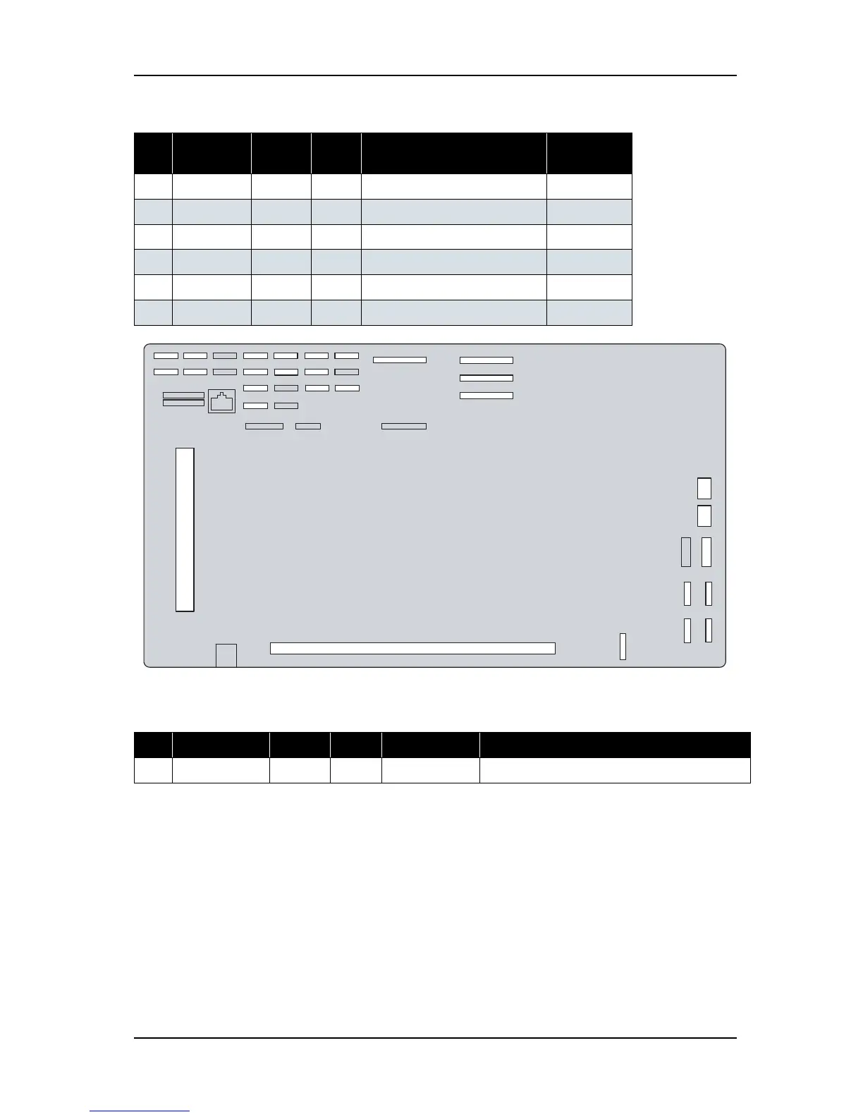
Table 4-3 Connectors to Main Board Assembly (Continued)
No. Connector
No.
# of pins Color Connect to Remarks
J17
J15
J8
J7
J43
J16
J18
J24
J28
J29
J2 J41
J39
J37
J35
J33
J12
J32
J5
J44
J34
J36
J40
J42
J27
J19
J14
KINK
MINK
REVINK1 CRORG WSENSER
WSENSEL
REVSENS1
REVSENS2
DEBUG
WIPEORG
LEVERSENS
COVERR
REVINK2
SERIALREV
CINK
YINK
J13
J3
SYSTEM
FPGAJTAG
PREAR
SENS
COVERL
PFENC
CFAN1
PANEL
TOCRJ201
TOCRJ202
TOCRJ203
CFAN2
CFAN3(+24V)
ISPJTAG
J11
J10
J9
DIMMCONNECTOR
USBIF
PCISLOT
J6
J20
PF
MOTOR
J1
POWERSUPPLY
CR
MOTOR
J21
J22
PUMP1
J23
PUMP2
J26
BLOWER
FAN2
BLOWER
FAN1
J25
J28
J29
MAIN board connection diagram