June 2014
4-20
Xerox® WorkCentre® 3215/3225 Multifunction Printer Service Manual
REP 1.10
Repairs
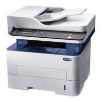
Figure 2 Front Cover Support Arm Placement
2. Reinstall the Main Drive Unit (5 screws).
NOTE: Make sure the Tabs (2) on the Locking Lever are inside the Frame cutouts before
moving the Fuser Drive Locking Lever to the Lock position.
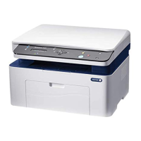
3. Align the Locking Lever Tabs (2) to the cutouts in the frame (Figure 3).
Figure 3 Locking Lever Tab and Frame Cutout
4. Press in on the Locking Lever to move the Tabs into the cutouts.
Move the Locking Lever to the Lock position (Left).
5. Install the remaining components in the reverse of removal.
Support Arm
Locking Lever
Tab and Cutout