7 Series FPGAs GTP Transceivers User Guide www.xilinx.com 199
UG482 (v1.9) December 19, 2016
RX Channel Bonding
Ports and Attributes
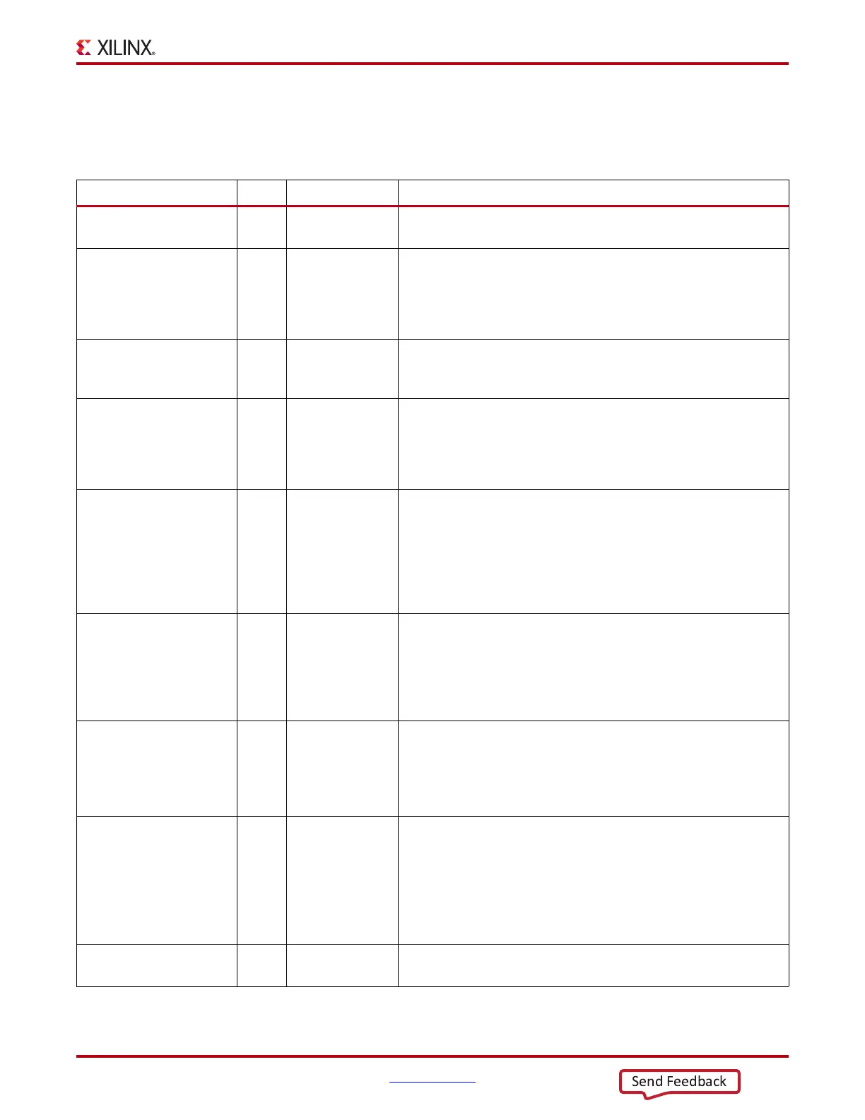
Table 4-39 defines the ports required by RX channel bonding functions.
Table 4-39: RX Channel Bonding Ports
Port Dir Clock Domain Description
RXCHANBONDSEQ Out RXUSRCLK2 This port goes High when RXDATA contains the start of a channel
bonding sequence.
RXCHANISALIGNED Out RXUSRCLK2 This signal from the RX elastic buffer goes High to indicate that the
channel is properly aligned with the master transceiver according to
observed channel bonding sequences in the data stream. This signal
goes Low if an unaligned channel bonding sequence is detected,
indicating that channel alignment was lost.
RXCHANREALIGN Out RXUSRCLK2 This signal from the RX elastic buffer is held High for at least one cycle
when the receiver has changed the alignment between this transceiver
and the master.
RXCHBONDI[3:0] In RXUSRCLK Channel bonding control ports used by slaves only. These ports are
used to receive channel bonding and clock correction control
information from master GTP transceiver RXCHBONDO ports or
from daisy-chained slave GTP transceiver RXCHBONDO ports,
which are concatenated from the master GTP transceiver.
RXCHBONDO[3:0] Out RXUSRCLK Channel bonding control ports used to propagate channel bonding and
clock correction information to the slave GTP transceiver from the
master or a daisy-chained slave concatenated from the master. The
master RXCHBONDO can be tied to one or multiple slave
RXCHBONDI ports. The slave RXCHBONDO should be tied to the
next level slave RXCHBONDI to form a daisy chain and pass
information from the master to each slave.
RXCHBONDLEVEL[2:0] In RXUSRCLK2 Indicates the amount of internal pipelining used for the RX elastic
buffer control signals. A higher value permits more daisy chaining of
RXCHBONDO and RXCHBONDI to ease placement and routing
constraints. To minimize required latency through the RX elastic
buffer, CHAN_BOND_LEVEL in the master is set to the smallest
value possible for the required amount of daisy-chaining.
RXCHBONDMASTER In RXUSRCLK2 Indicates that the transceiver is the master for channel bonding. Its
RXCHBONDO port directly drives the RXCHBONDI ports on one or
more slave transceivers.
This port cannot be driven High at the same time as
RXCHBONDSLAVE.
RXCHBONDSLAVE In RXUSRCLK2 Indicates that this transceiver is a slave for channel bonding. Its
RXCHBONDI port is directly driven by the RXCHBONDO port of
another slave or master transceiver. If its RXCHBONDLEVEL[2:0]
setting is greater than 0, its RXCHBONDO port can directly drive the
RXCHBONDI ports on one or more other slave transceivers.
This port cannot be driven High at the same time as
RXCHBONDMASTER.
RXCHBONDEN In RXUSRCLK2 This port enables channel bonding (from the FPGA logic to both the
master and slaves).