204 www.xilinx.com 7 Series FPGAs GTP Transceivers User Guide
UG482 (v1.9) December 19, 2016
Chapter 4: Receiver
port of the master. The following steps describe how to set the RXCHANBONDLEVEL for the
GTP transceivers in the chain:
1. Set the RXCHANBONDLEVEL of the master to 7.
2. Set the RXCHANBONDLEVEL of each slave to the RXCHANBONDLEVEL of the GTP
transceiver driving the slave’s RXCHBONDI port minus 1.
3. Find the slave with the lowest level. Subtract this level from the RXCHANBONDLEVEL of all
GTP transceivers so that the lowest slave has level 0 and the master has the minimum level
required to service all the slaves.
When the connections between channel bonding ports among GTP transceivers are being decided,
the designer must remember that RXCHBONDI and RXCHBONDO belong to the RXUSRCLK
clock domain. Meeting the timing constraint of RXUSRCLK becomes increasingly difficult as
RXUSRCLK increases in frequency and as directly connected transceivers get further apart.
GTP transceivers in the same half of the device can be bonded with each other. A GTP transceiver
located in the top half of the device can be bonded with other GTP transceivers located transceivers
in the top half. A GTP transceiver located in the bottom half of the device cannot be bonded with a
GTP transceiver located in the top half of the device.
As long as timing constraints are met, there is no limit to the number of GTP transceivers that can be
on a particular RXCHANBONDLEVEL.
Setting Channel Bonding Sequences
The channel bonding sequence is programmed in the same way as the clock correction sequence.
CHAN_BOND_SEQ_LEN sets the length of the sequence, and CHAN_BOND_SEQ_1_* sets the
values of the sequence. If CHAN_BOND_SEQ_2_USE is TRUE, CHAN_BOND_SEQ_2_* sets
the values for the alternate second sequence. The number of active bits in each subsequence depends
on RX_DATA_WIDTH and CBCC_DATA_SOURCE_SEL (see RX Clock Correction, page 191).
When RX_DISPERR_SEQ_MATCH is set to FALSE, CHAN_BOND_SEQ_x_y[9] is not used for
matching.
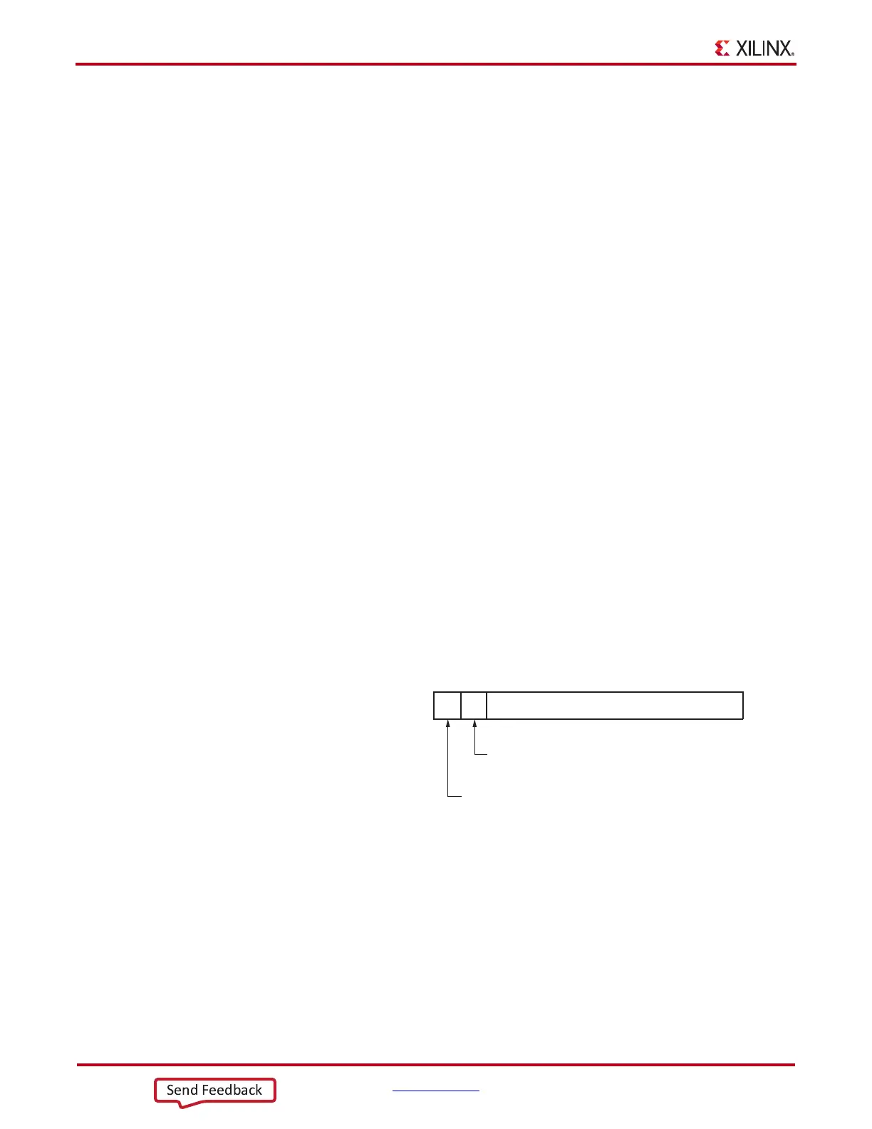
Figure 4-50 shows how the subsequence bits are mapped.
As with clock correction sequences, channel bonding sequences can have don’t care subsequences.
CHAN_BOND_SEQ_1_ENABLE and CHAN_BOND_SEQ_2_ENABLE set these bytes.
Figure 4-51 shows the mapping of the enable attributes for the channel bonding subsequences.
X-Ref Target - Figure 4-50
Figure 4-50: Channel Bonding Sequence Settings
CHAN BOND_SEQ_x_y
8-Bit Channel Bonding Sequence
1 = Sequence Uses Inverted Disparity
0 = Sequence Uses Regular Disparity
7:089
1 = Sequence is a K Character
0 = Sequence is a Regular Character
UG482_c4_32_111011
 Loading...


