7 Series FPGAs GTP Transceivers User Guide www.xilinx.com 37
UG482 (v1.9) December 19, 2016
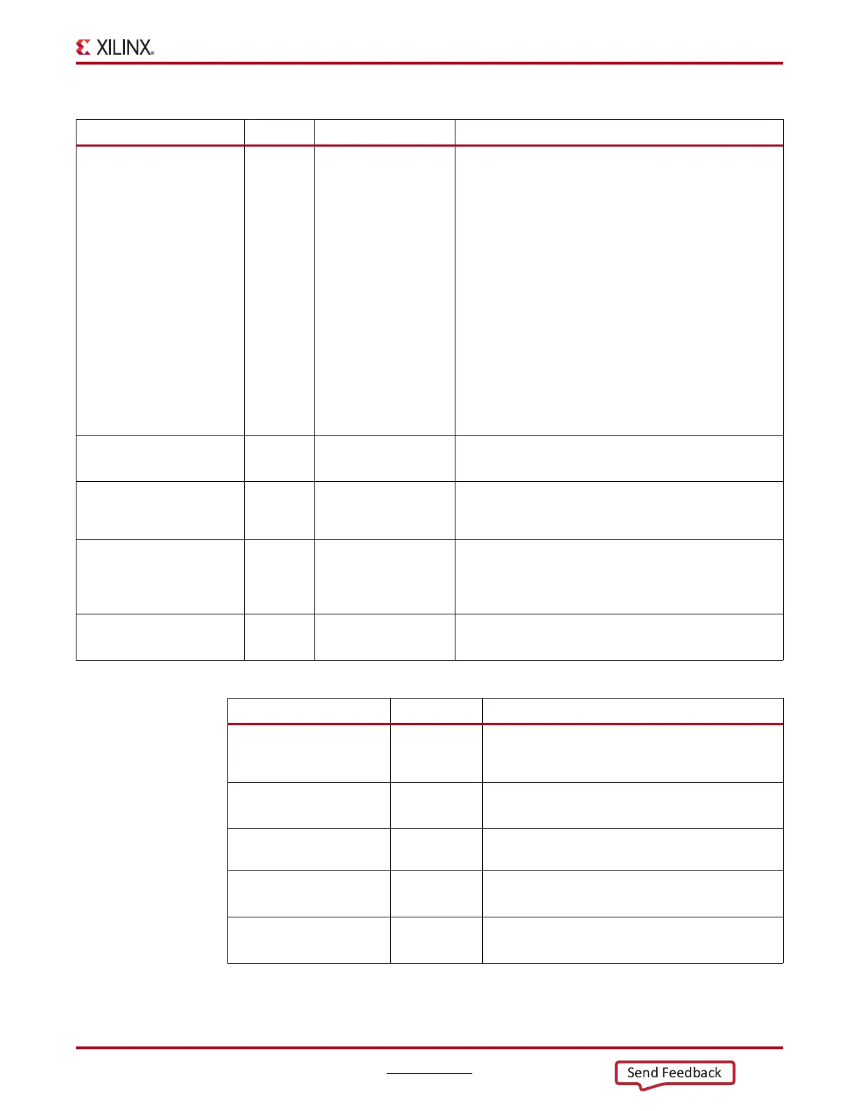
PLL
PLL0REFCLKSEL[2:0]
PLL1REFCLKSEL[2:0]
In Async Input to dynamically select the input reference clock to the
PLL. This input should be set to 3'b001 when only one
clock source is connected to the PLL reference clock
selection multiplexer.
Reset must be applied to the PLL after changing the
reference clock input.
000: Reserved
001: GTREFCLK0 selected
010: GTREFCLK1 selected
011: GTEASTREFCLK0 selected
100: GTEASTREFCLK1 selected
101: GTWESTREFCLK0 selected
110: GTWESTREFCLK1 selected
111: GTGREFCLK0 (PLL0) or GTGREFCLK1
(PLL1) selected
PLL0RESET
PLL1RESET
In Async This active-High port resets the dividers inside the PLL as
well as the PLL lock indicator and status block.
PLL0FBCLKLOST
PLL1FBCLKLOST
Out PLL0LOCKDETCLK
PLL1LOCKDETCLK
A High on this signal indicates the feedback clock from the
PLL feedback divider to the phase frequency detector of the
PLL is lost.
PLL0LOCK
PLL1LOCK
Out Async This active-High PLL frequency lock signal indicates that
the PLL frequency is within predetermined tolerance. The
transceiver and its clock outputs are not reliable until this
condition is met.
PLL0REFCLKLOST
PLL1REFCLKLOST
Out PLL0LOCKDETCLK
PLL1LOCKDETCLK
A High on this signal indicates the reference clock to the
phase frequency detector of the PLL is lost.
Table 2-8: PLL Ports (Cont’d)
Port Direction Clock Domain Description
Table 2-9: PLL Attributes
Attribute Type Description
PLL0_CFG
PLL1_CFG
27-bit Hex Reserved. Configuration setting for the PLL. The
recommended value from the 7 Series FPGAs
Transceivers Wizard should be used.
PLL0_FBDIV
PLL1_FBDIV
Integer
PLL feedback divider setting as shown in Figure 2-10,
page 35. Valid settings are 1, 2, 3, 4, and 5.
PLL0_FBDIV_45
PLL1_FBDIV_45
Integer PLL feedback divider settings as shown in
Figure 2-10, page 35. Valid settings are 4 and 5.
PLL0_LOCK_CFG
PLL1_LOCK_CFG
9-bit Hex
Reserved. The recommended value from the 7 Series
FPGAs Transceivers Wizard should be used.
PLL0_REFCLK_DIV
PLL1_REFCLK_DIV
Integer
PLL reference clock divider M settings as shown in
Figure 2-10, page 35. Valid settings are 1 and 2.