44 www.xilinx.com 7 Series FPGAs GTP Transceivers User Guide
UG482 (v1.9) December 19, 2016
Chapter 2: Shared Features
2. GTTXRESET must be used.
3. TXPMARESET and TXPCSRESET must be constantly driven Low during the entire reset
process before TXRESETDONE is detected High.
4. GTTXRESET cannot be driven Low until the associated PLL is locked.
If the reset mode is defaulted to sequential mode upon configuration, then PLL[0/1]RESET and
GTTXRESET can be asserted after waiting for a minimum of 500 ns after configuration is
complete.
If the reset mode is defaulted to single mode, then the user must:
1. Wait a minimum of 500 ns after configuration is complete.
2. Change reset mode to Sequential mode.
3. Wait another 300-500 ns.
4. Assert PLL[0/1]RESET and GTTXRESET.
It is recommended to use the associated PLLLOCK from either PLL0 or PLL1 to release
GTTXRESET from High to Low as shown in Figure 2-14. The TX reset state machine waits when
GTTXRESET is detected High and starts the reset sequence when GTTXRESET is released Low.
GTP Transceiver TX Reset in Response to GTTXRESET Pulse
The GTP transceiver allows the user to reset the entire TX completely at any time by sending
GTTXRESET an active-High pulse. TXPMARESET_TIME and TXPCSRESET_TIME can be set
statically or reprogrammed through DRP ports to adjust the required reset time before applying
GTTXRESET. These conditions must be met when using GTTXRESET:
1. GTRESETSEL must be driven Low to use sequential mode.
2. TXPMARESET and TXPCSRESET must be driven constantly Low during the entire reset
process before TXRESETDONE is detected High.
3. The associated PLL must indicate locked.
4. The guideline for this asynchronous GTTXRESET pulse width is one period of the reference
clock.
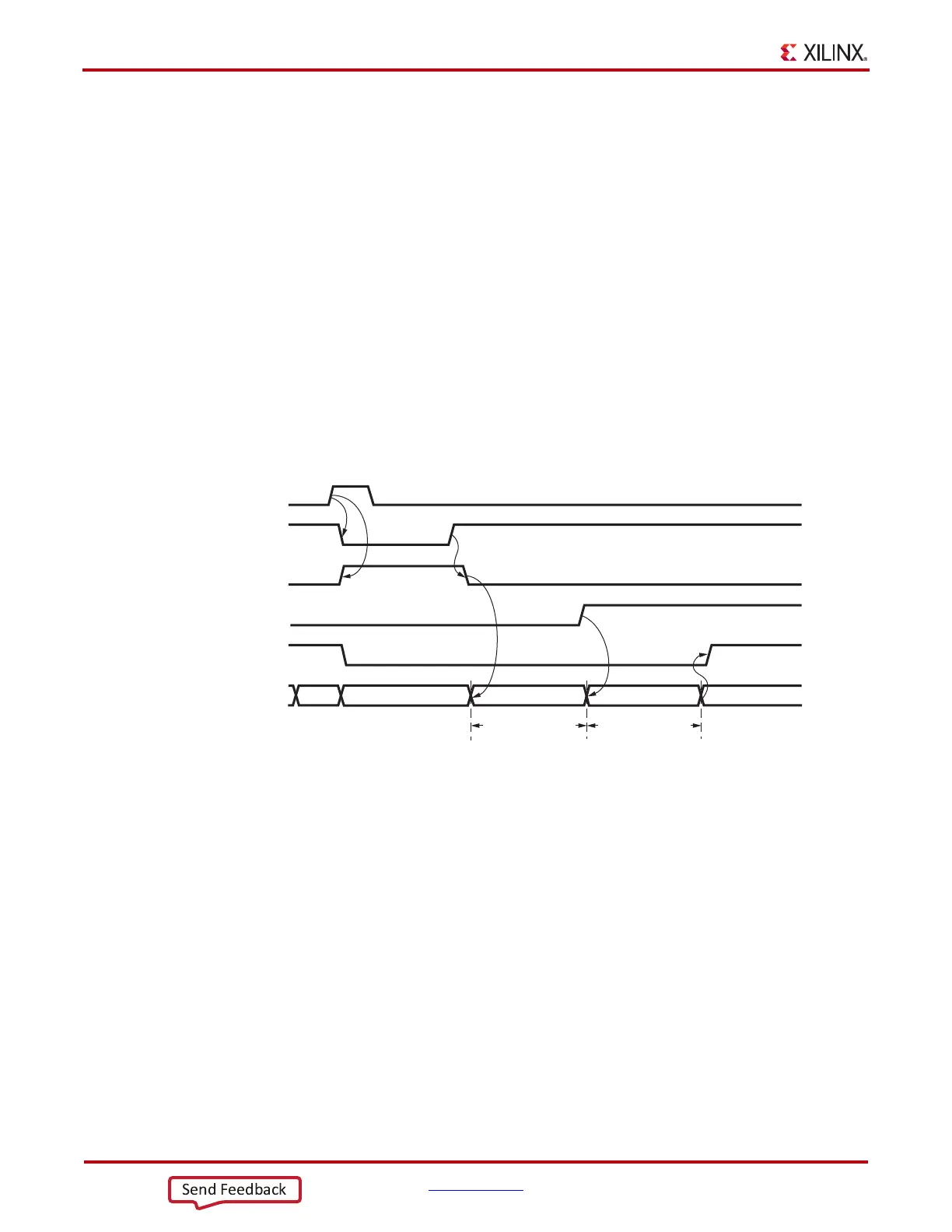
X-Ref Target - Figure 2-14
Figure 2-14: GTP Transceiver Transmitter Initialization after FPGA Configuration
PLL0RESET/PLL1RESET
PLL0LOCK/PLL1LOCK
GTTXRESET
TXUSERRDY
TXRESETDONE
TX RESET FSM IDLE IDLEWAIT TXPMARESET TXPCSRESET
TXPMARESET_TIME TXPCSRESET_TIME
UG482_c2_114_102914