7 Series FPGAs GTP Transceivers User Guide www.xilinx.com 43
UG482 (v1.9) December 19, 2016
Reset and Initialization
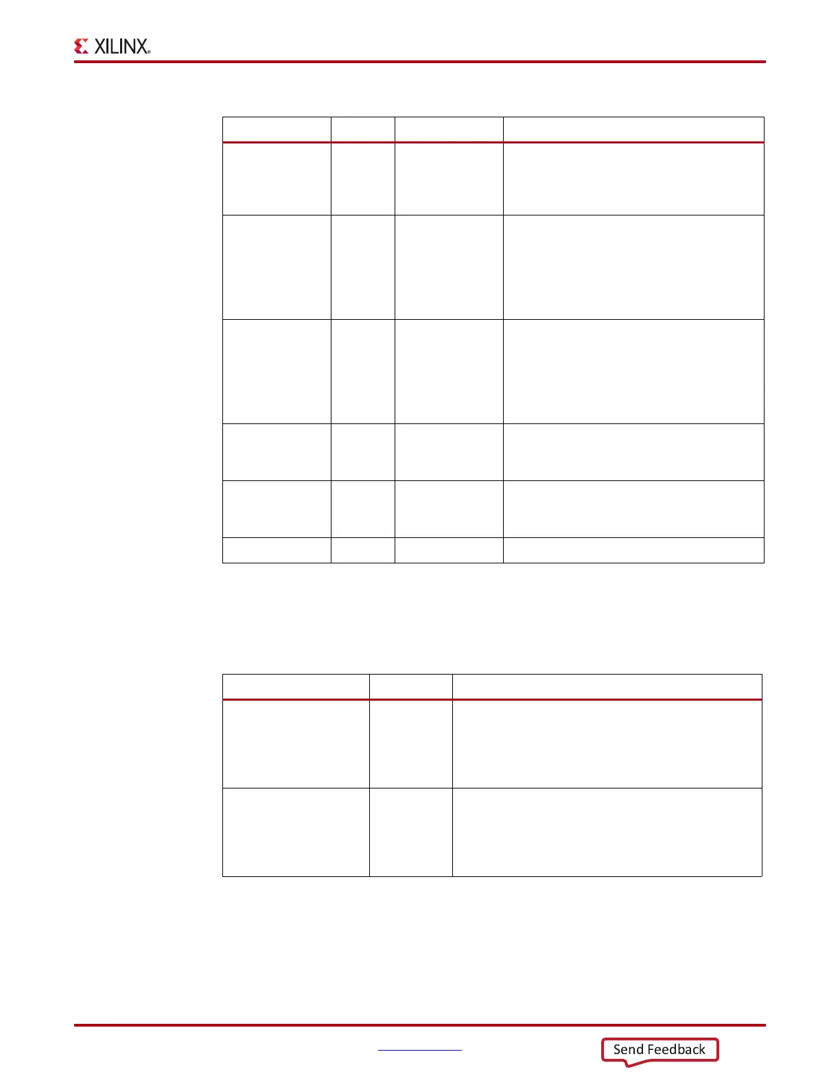
Table 2-15 lists attributes required by the GTP transceiver’s TX initialization. In general cases, the
reset time required by the TX PMA or the TX PCS varies depending on line rate. The factor
affecting PMA reset time and PCS reset time are user-configurable attributes
TXPMARESET_TIME and TXPCSRESET_TIME.
GTP Transceiver TX Reset in Response to Completion of Configuration
The TX reset sequence shown in Figure 2-13 is not automatically started to follow global GSR. It
must meet these conditions:
1. GTRESETSEL must be Low to use sequential mode.
TXPCSRESET In Async This port is used to reset the TX PCS. It is driven
High and then deasserted to start the PCS reset
process. In sequential mode, activating this port
only resets the TX PCS.
TXUSERRDY In Async This port is driven High from the user's
application when TXUSRCLK and
TXUSRCLK2 are stable. For example, if an
MMCM is used to generate both TXUSRCLK
and TXUSRCLK2, then the MMCM lock signal
can be used here.
TXRESETDONE Out TXUSRCLK2 This active-High signal indicates the GTP
transceiver TX has finished reset and is ready
for use. This port is driven Low when
GTTXRESET goes High and is not driven High
until the GTP transceiver TX detects
TXUSERRDY High.
TXPMARESETD
ONE
Out Async This active-High signal indicates GTP TX PMA
reset is complete. This port is driven Low when
GTTXRESET or TXPMARESET is asserted.
CFGRESET In Async Reserved. The recommended value from the
7 Series FPGAs Transceivers Wizard should be
used.
PCSRSVDOUT Out Async Reserved.
Table 2-15: TX Initialization and Reset Attributes
Attribute Type Description
TXPMARESET_TIME 5-bit Binary Reserved. Represents the time duration to apply a TX
PMA reset. The recommended value from the 7 Series
FPGAs Transceivers Wizard should be used. Must be a
non-zero value when GTTXRESET or TXPMARESET is
used to initiate the reset process.
TXPCSRESET_TIME 5-bit Binary Reserved. Represents the time duration to apply a TX
PCS reset. The recommended value from the 7 Series
FPGAs Transceivers Wizard should be used. Must be a
non-zero value when TXPCSRESET is used to initiate
the reset process.
Table 2-14: TX Initialization and Reset Ports (Cont’d)
Port Dir Clock Domain Description