117
0: Line VF
Suitable for common constant torque load.
1: Multi-point VF
Suitable for dehydrator, centrifuge and other special loads. By setting P5-01 ~ P5-06 parameters, any VF
relation curve can be obtained.
2: Square VF
Suitable for centrifugal loads such as fans and pumps.
3: the 1.2
nd
power VF||4: the 1.4
th
power VF||6: the 1.6
th
power VF||8: the 1.8
th
power VF
VF relationship curve between line VF and square VF.
10: VF complete separation mode
The output frequency and voltage of the inverter are independent of each other. The output frequency is
determined by the frequency source and the output voltage is determined by P5-09 (VF separated voltage
source).
11: VF half separation mode
In the VF half separation mode, V and F are proportional, but the proportional relationship can be set through
the voltage source P5-09, and the relationship between V and F is also related to the rated voltage and rated
frequency of the motor in group F1.
The relationship between VFD output voltage V and frequency F:
, A is percentage of voltage source input (0~100%).
Multi-point VF frequency point F1
Multi-point VF voltage point V1
Multi-point VF frequency point F2
Multi-point VF voltage point V2
Multi-point VF frequency point F3
P5-05~ (motor rated frequency) P1-04
Multi-point VF voltage point V3
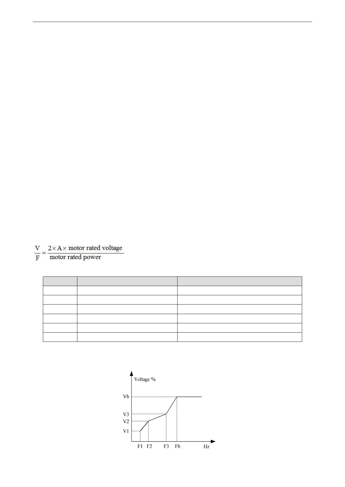
When P5-00 = 1, the VF curve user-defined multi-point VF curve, as shown in the figure below, the user uses
(V1, F1), (V2, F2), (V3, F3) three-point broken line mode to define the VF curve to adapt to the special load
requirements.
 Loading...