45
3-7. VFD counting function
In the application, the corresponding input terminal function needs to be set as "counter input" (function 20).
When the pulse frequency is high, the X4 port must be used.
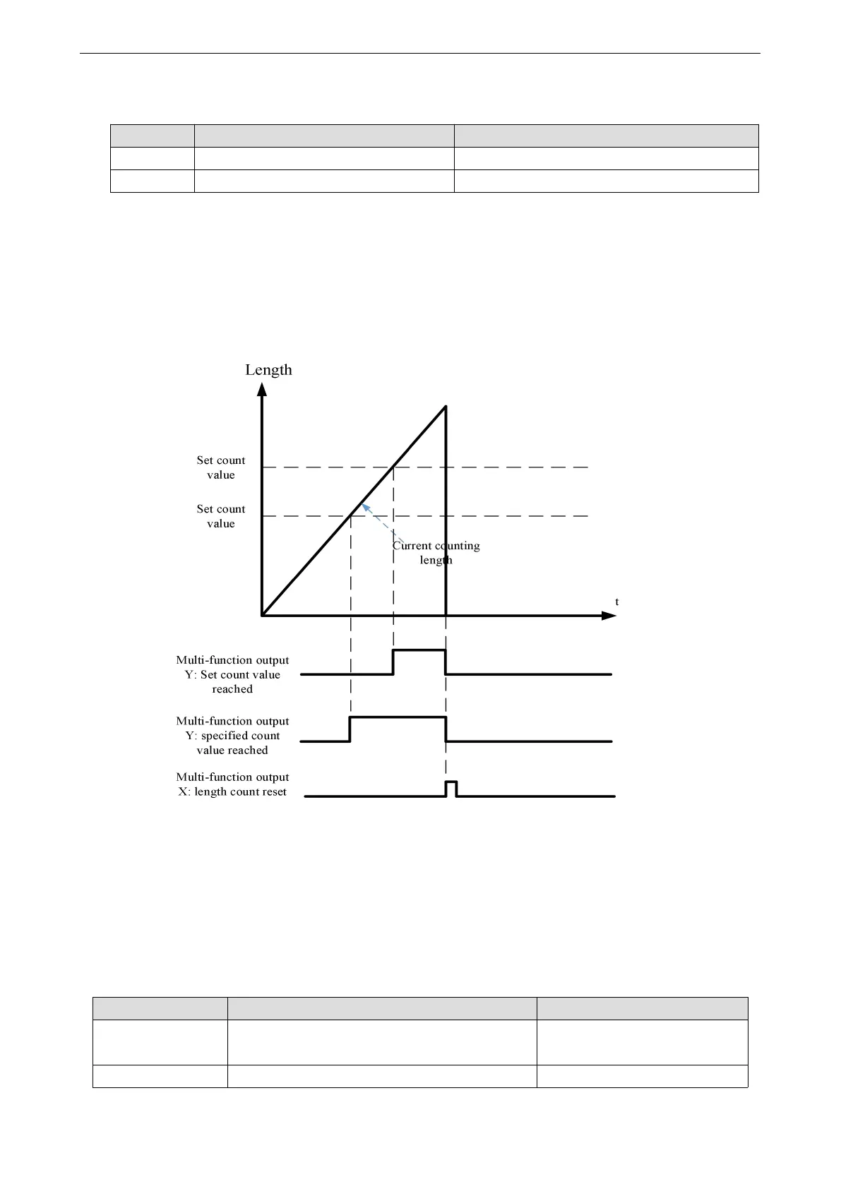
When the count value reaches the specified count value A0-04, the multi-function digital Y outputs the
"specified count value reaches" on signal. At this time, the counter continues to count. When the count value
reaches the set count value A0-03, the multi-function digital Y outputs the "set count value reaches" on signal.
The count value can be reset through the multi-function X terminal (function 21). The function sequence
diagram is as follows:
3-8. Motor parameters and tuning
3-8-1. Motor parameter setting
When the inverter operates in vector control (P0-01 = 1 or 2) mode, it is required to set correct motor
parameters, which is different from VF (P0-01 = 0) mode.
Motor rated power / voltage / current / frequency
/ speed
Model parameters, manual input
Equivalent stator resistance, inductance and rotor
Tuning parameters, tuning
 Loading...