Xtreme Power Conversion Corporaon
TX90 6kVA & 10kVA Service Manual
Page 26
Uninterrupble Power Supply
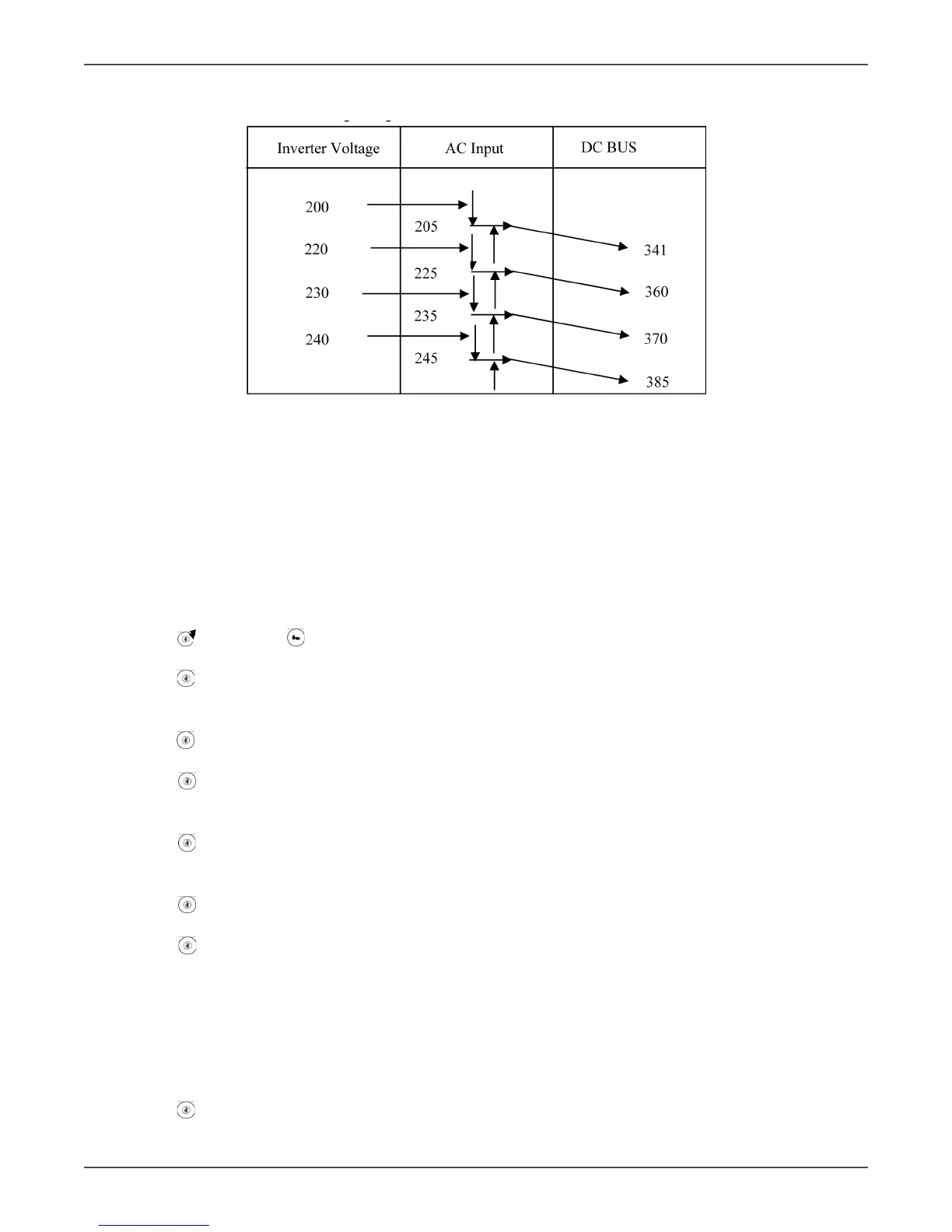
DC BUS Voltage Regulaon
Startup Procedure for Debug UPS
• Connect an AC 220Vac/50(60)Hz onto L11 & L12.
• Remove the output loads connected to the UPS and remove the baery connecng wires of the UPS.
• Remove the Fuse of ulity input (TX90-6K : F2 of the MSDD0XX PCB, TX90-10K : F1 and F2 of the MSEF4XX).
• Remove the control wires CN13 & CN14 of the MSDC0XX PCB and measure the DC Bus voltage by using
mul-meter. (MSDD0XX PCB: Bus + is to measure CN19 to the upper end of C38 and Bus – is to measure
CN19 to the upper end of C37, MSEB0XX PCB : Bus + is to measure CN1 to CN2 and Bus – is to measure
CN2 to CN23.)
• Turn o CB2 and turn on CB1 for 6K/10K, ulity breaker for 20K.
• Push
key pad and key pad for approx. 3 seconds ll buzzer beeps twice, then the UPS will go to ser-
vice mode.
• Push key pad for a second ll the buzzer beeps twice, and LCD displays from Sr01 to Sr02. Measure the
waveform of the PFC and Inverter IGBT gate, it shall be a square wave with voltage/frequency at -6Vdc ~
+15Vdc / 20KHz, then buzzer will beep once.
• Push key pad for a second ll buzzer beeps twice. The LCD displays from Sr02 to Sr03, then the UPS pro-
ceeds the 1st stage so start, which means charger is charging the BUS + & -, then buzzer will beep once.
• Push key pad for a second ll buzzer beeps twice. The LCD displays from Sr03 to Sr04, then the UPS
proceeds the 2nd stage so start, which means baery SCR is turned on to charge the BUS + & -, then the
buzzer will beep once.
• Push key pad for a second ll buzzer beeps twice. The LCD displays from Sr04 to Sr05, then UPS pro-
ceeds the 3rd stage so start, which means the DC voltage is boosted up to the desired voltage, then the
buzzer will beep once.
• Push key pad for a second ll buzzer beeps twice. The LCD displays from Sr05 to Sr06, then the UPS
proceeds the voltage seng from Inverter So Start to Inverter Output, then the buzzer will beep once.
• Push key pad for a second ll buzzer beeps twice. The LCD displays form SR06 to OFF, then the UPS
proceeds DC Bus discharging. The UPS will shut itself o automacally aer discharged.
• Turn o CB1 and put the Fuse of ulity input back.
• Turn on both CB1 and CB2
• The LCD displays “oFF”, then measure the output of the UPS is nominal voltage such as 220Vac/50(60Hz)
or not.
• Adjust the voltage of Bypass Input at 170Vac/50(60)Hz and check if the UPS output voltage is near 0Vac?
• Adjust the voltage of Bypass Input at nominal voltage such as 220Vac/50(60)Hz.
• Push key pad for 3 seconds unl buzzer beeps twice, then the UPS proceeds AC start procedure. When
self-test is executed completely, the UPS will switch from bypass output to Inverter output. Measure the