Xtreme Power Conversion Corporaon
TX90 6kVA & 10kVA Service Manual
Page 19
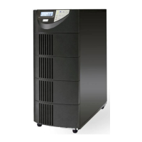
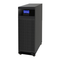
Uninterrupble Power Supply
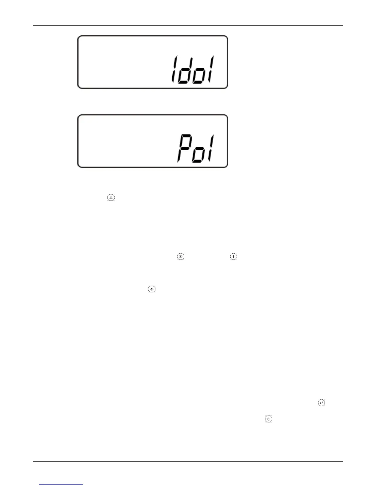
X
UPS posion in parallel mode
Y
The parallel funcon is disabled.
• Press the scroll up key to execute special funcons. The funcons include buzzer ON (as in gure Q1),
buzzer OFF (as in gure Q2, Alarm silence for UPS Warning), and self-test OFF (as in gure R). The UPS will
execute the baery test for ten seconds. If the self-test is successful it will display gure E1; otherwise, it
will display gure E2 and an error message at the same me.)
Changing the UPS Default Sengs
• Make sure the UPS is not “On”. Press the On and scroll down keys simultaneously for approximately
three seconds. The buzzer will sound twice, and the LCD will display gure Q1, indicang that the UPS is
in seng mode.
• Except for Buzzer (gures Q1 and Q2) and Self-test (gure R) all of the other default sengs may be
changed by pressing the scroll up key.
• Figure S indicates the bypass input acceptable window. It can be 184-260 VAC or 195-260 VAC.
• Figure T indicates the bypass frequency window of the Inverter Output. The acceptable seng values are
±3 Hz and ±1 Hz.
• Figure U indicates the acceptable Inverter Output Voltage. Possible values are 200, 208, 220, 230, or 240
VAC. The inverter output voltage needs to match the input voltage for this system.
• Figure V indicates the operaon modes of the UPS. Possible values are Online, Eco (Economy) mode, xed
50 Hz Output, and xed 60 Hz Output.
• Figure W indicates the adjustment of the Inverter Output voltage, which may be set to 0%, +1%, -1%, +2%,
-2%, +3%, or -3%.
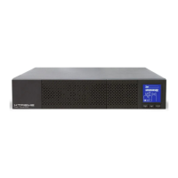
• Figure X indicates the posion of the UPS when the UPS is in Parallel mode. Possible posions are 1, 2, 3,
and 4. The posion must be 1 if the UPS is not in Parallel mode.
• Figure Y indicates the parallel funcon status. “P 01” indicates that the parallel funcon is disabled, and “P
02” indicates that the parallel funcon is enabled.
• Aer changing sengs you must scroll to the “SAVE” screen (gure Z) and then press the enter key to
save all of your changes. Then the LCD will display gure AA to indicate compleon of the seng changes.
To cancel your changes rather than save them press and hold the “OFF” key for ve seconds. The LCD
displays gure AA directly, which indicates that your changes were canceled.