330 Appendix A: Parameter Lists
DM2000—Owner’s Manual
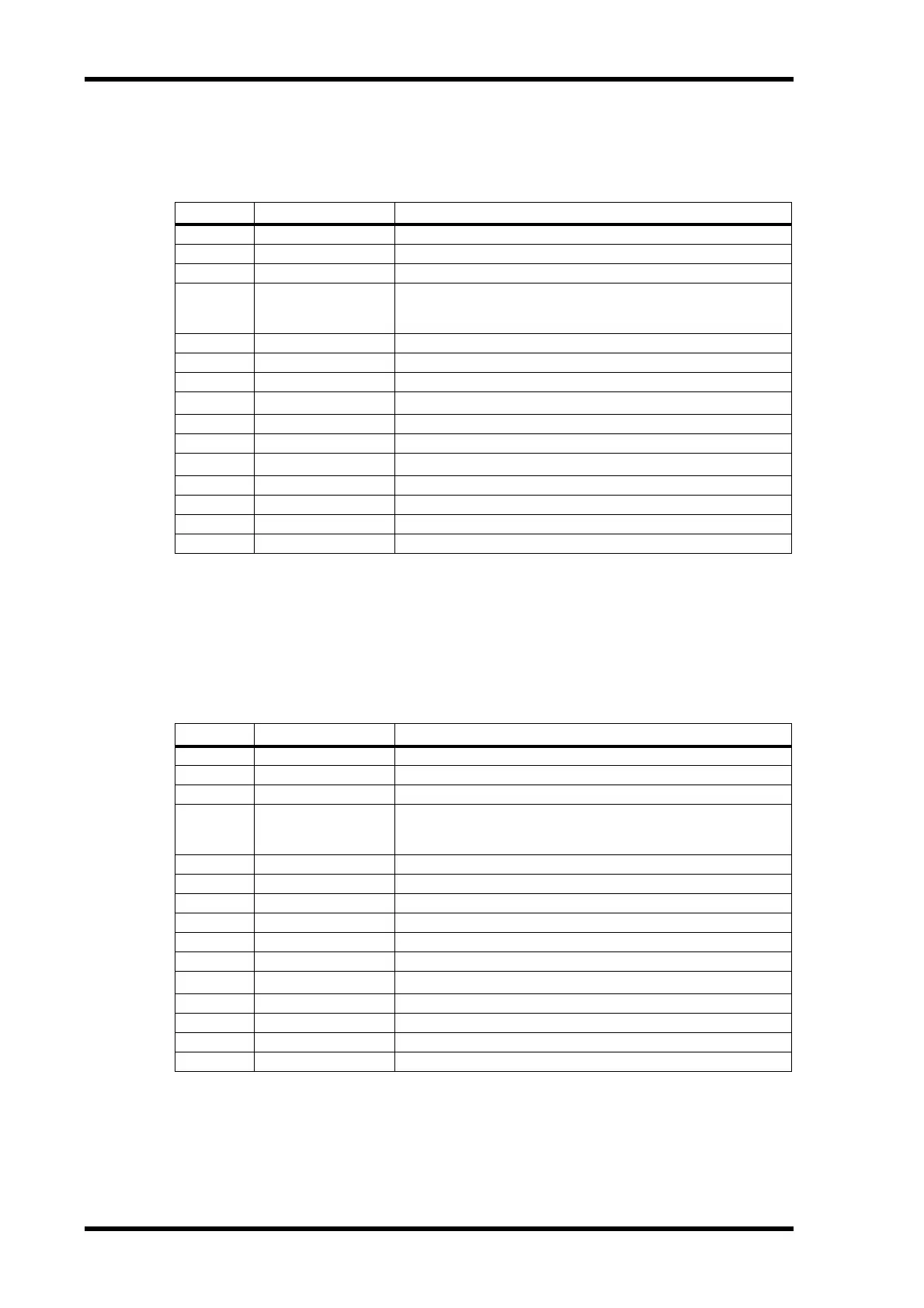
COMP 5.1
Six input, six output compressor for 5.1 surround, with individual solo for each band, and gain
reduction metering of left and right (L+R), left surround and right surround (LS+RS), center (C),
or LFE channels.
COMPAND 5.1
Six input, six output compander for 5.1 surround, with individual solo for each band, and gain
reduction metering of left and right (L+R), left surround and right surround (LS+RS), center (C),
or LFE channels.
Other preset effects (COMP276, COMP276S, COMP260, COMP260S, EQUALIZER601, OPEN-
DECK, REV-X HALL, REV-X HALL, REV-X ROOM, REV-X PLATE) are optional Add-On
Effects. For more information on these effects, refer to the Owner’s Manual that comes with the
Add-On Effects package.
Parameter Range Description
LOW GAIN –96.0 to +12.0 dB Low band level
MID GAIN –96.0 to +12.0 dB Mid band level
HI. GAIN –96.0 to +12.0 dB High band level
PRESENCE –10 to +10
For positive values, the threshold of the high band is lowered and the
threshold of the low band is increased. For negative values, the oppo-
site will occur. When set to 0, all three bands are affected the same.
THRE –24.0 dB to 0.0 dB Compressor threshold
RATIO 1:1 to ∞:1 Compressor ratio
ATTACK 0–120 ms Attack
RELEASE
1
1. 6.0 ms–46.0 s (fs=44.1 kHz), 5.0 ms–42.3 s (fs=48 kHz), 3 ms–23.0 s (fs=88.2 kHz), 3 ms–21.1 s (fs=96 kHz)
Expander release time
KNEE 0–5 Compressor knee
LOOKUP 0.0–100.0 ms Lookup delay
KEY LINK
2
2. 5.1: key-in of all inputs are linked. 5.0: key-in of the L, C, R, LS, and RS are linked (LFE is independent). 3+2: key-in
of L, C, and R are linked, and LS and RS are linked. 2+2: key-in of L and R are linked, and LS and RS are linked.
Key-in linking
L–M XOVR 21.2 Hz–8.00 kHz Low/mid crossover frequency
M–H XOVR 21.2 Hz–8.00 kHz Mid/high crossover frequency
SLOPE –6 dB, –12 dB Filter slope
CEILING –6.0 dB to 0.0 dB, OFF Specifies the maximum output level
Parameter Range Description
LOW GAIN –96.0 to +12.0 dB Low band level
MID GAIN –96.0 to +12.0 dB Mid band level
HI. GAIN –96.0 to +12.0 dB High band level
PRESENCE –10 to +10
For positive values, the threshold of the high band is lowered and the
threshold of the low band is increased. For negative values, the oppo-
site will occur. When set to 0, all three bands are affected the same.
THRE –24.0 dB to 0.0 dB Compressor threshold
RATIO 1:1 to 20:1 Compressor ratio
ATTACK 0–120 ms Compressor attack
WIDTH 1–90 dB Width before the expander operates
TYPE Soft, Hard Compander type
LOOKUP 0.0–100.0 ms Lookup delay
KEY LINK
1
1. 5.1: key-in of all inputs are linked. 5.0: key-in of the L, C, R, LS, and RS are linked (LFE is independent). 3+2: key-in
of L, C, and R are linked, and LS and RS are linked. 2+2: key-in of L and R are linked, and LS and RS are linked.
Key-in linking
L–M XOVR 21.2 Hz–8.00 kHz Low/mid crossover frequency
M–H XOVR 21.2 Hz–8.00 kHz Mid/high crossover frequency
SLOPE –6 dB, –12 dB Filter slope
CEILING –6.0 dB to 0.0 dB, OFF Specifies the maximum output level