3-44
1
2
3
4
5
6
7
8
9
10
ENGINE
PISTON, CAMSHAFT, CRANKCASE, AND CRANKSHAFT
4.
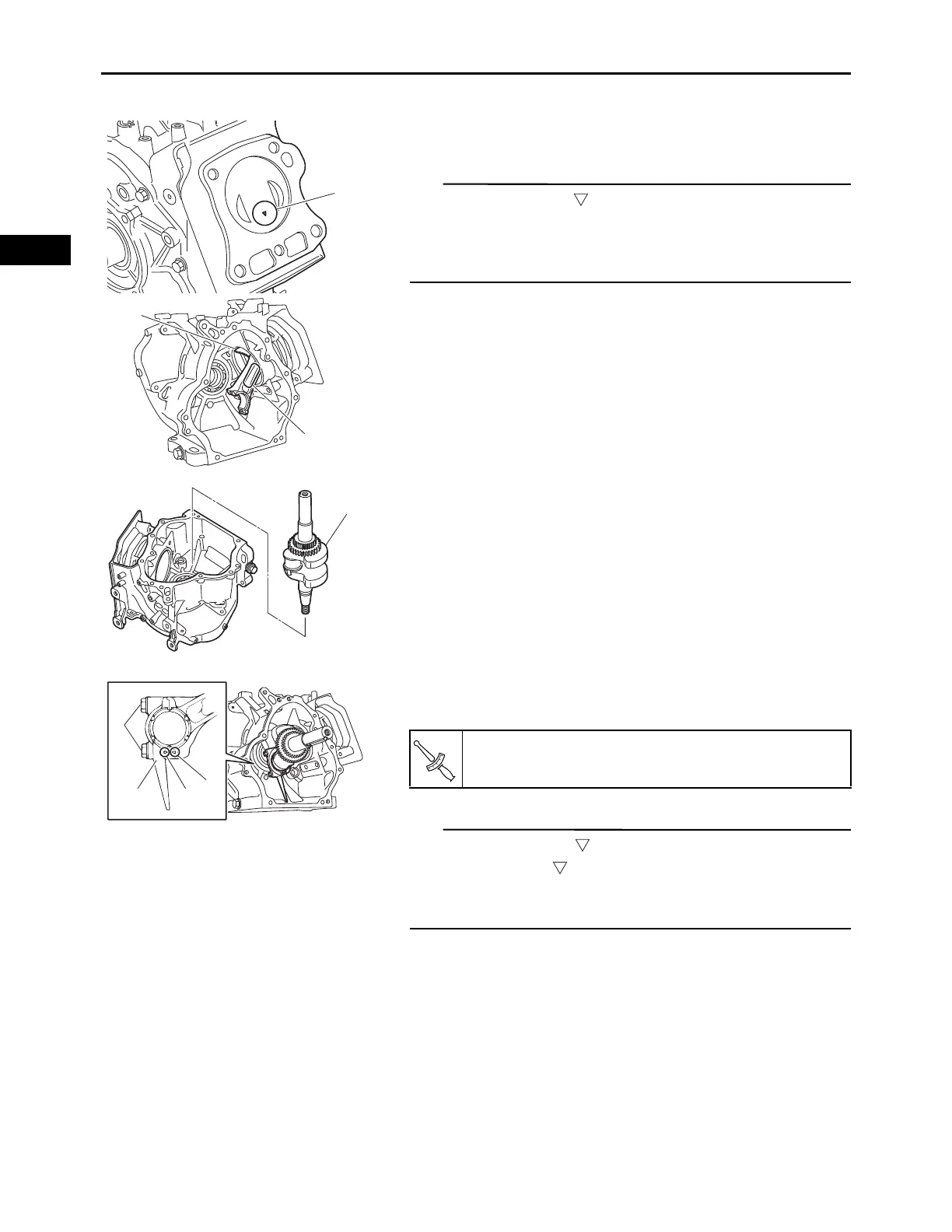
Check:
• Piston with the connecting rod “1” position
• Make sure that the “ ” mark “a” on the piston head faces
toward the push rod.
• Make sure that the “YAMAHA” mark “b” on the connect-
ing rod faces toward the crankcase cover.
5.
Install:
• Crankshaft “1”
6.
Install:
• Connecting rod cap “1”
• Connecting rod cap bolts “2”
• Make sure that the “ ” mark “a” on the connecting rod is
aligned with the “ ” mark “b” on the connecting rod cap.
• Tighten the connecting rod cap bolts alternately two to
three times.
7.
Install:
• Camshaft
(Refer to “INSTALLING THE VALVE LIFTER AND
CAMSHAFT” on page 3-36)
• Crankcase cover
(Refer to “INSTALLING THE CRANKCASE
COVER” on page 3-36)
Connecting rod cap bolt:
20 N·m (2.0 kgf·m, 15 lb·ft)