7 Wiring
7.2.5 I/O Signals
7-28
7.2.5 I/O Signals
(1) Connections
Connector Pin Arrangement (CN1) for I/O Signals of the Power Regeneration Converter
∗ Do not use NC signal.
Connector Pin Arrangement (CN1) for I/O Signals of the SERVOPACK for One Axis
∗1. Do not use NC signal.
∗2. Use CN1 or CN3 for motor winding temperature detection.
Do not use CN1 on the SERVOPACK as the I/O signal for an emergency stop.
Use CN1 on the power regeneration converter.
Pin No.
Signal
Name
I/O Function Pin No.
Signal
Name
I/O Function
1 /MCON+ O
Main circuit connector
ON output
8
*
(NC) – –
2 /MCON– O
Main circuit connector
ON output
9
*
(NC) – –
3
*
(NC) – –
10
*
(NC) – –
4
*
(NC) – – 11 /ESP+ I Emergency stop input
5
*
(NC) – – 12 /ESP– I Emergency stop input
6
*
(NC) – –
13
*
(NC) – –
7
*
(NC) – –
14
*
(NC) – –
Pin No.
Signal
Name
I/O Function Pin No.
Signal
Name
I/O Function
1 COM24V I
+24V external power
supply input
14
*1
(NC) – –
2 /Probe1 I
Probe 1 latch signal
input
15
*1
(NC) – –
3 /Probe2 I
Probe 2 latch signal
input
16
*1
(NC) – –
4 /Home I Home switch input 17 /HWBB1– I Baseblock input 1
5
*1
(NC) – – 18 /HWBB1+ I Baseblock input 1
6 P-OT1 I Forward overtravel 19 /HWBB2– I Baseblock input 2
7 N-OT1 I Reverse overtravel 20 /HWBB2+ I Baseblock input 2
8
*1
(NC) – – 21 EDM1– O
Baseblock monitoring
signal
9 /BK1+ O Brake 22 EDM1+ O
Baseblock monitoring
signal
10 /BK1– O Brake 23 DBA1 I
External dynamic
brake answer signal
11
*2
THM1+ I
Motor winding temper-
ature detection
24 DBA2 I
External dynamic
brake answer signal
12
*2
THM1– I
Motor winding temper-
ature detection
25 DBON O
External dynamic
brake
13
*1
(NC) – – 26 DB24V O
External dynamic
brake
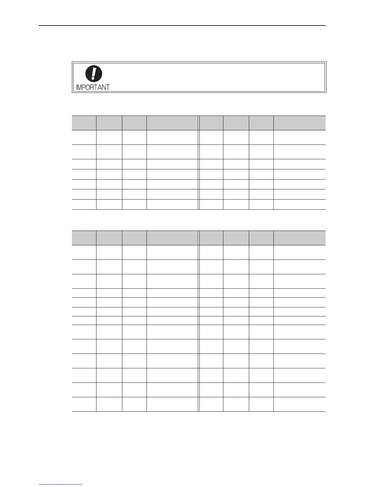 Loading...


