3 Specifications and External Dimensions for Motors
3.2.5 Allowable Load Moment of Inertia at the Motor Shaft
3-22
3.2.5 Allowable Load Moment of Inertia at the Motor Shaft
The rotor moment of inertia ratio is the value for a servomotor without a holding brake.
The larger the load moment of inertia, the worse the movement response of the load.
The allowable load moment of inertia (J
L
) depends on the motor capacity, as shown below. This value is pro-
vided strictly as a guideline and results may vary depending on servomotor drive conditions.
An overvoltage alarm (A.400) is likely to occur during deceleration if the load moment of inertia exceeds the
allowable load moment of inertia. Take one of the following steps if an overvoltage alarm occurs.
•Reduce the torque limit.
•Reduce the deceleration rate.
•Reduce the maximum speed.
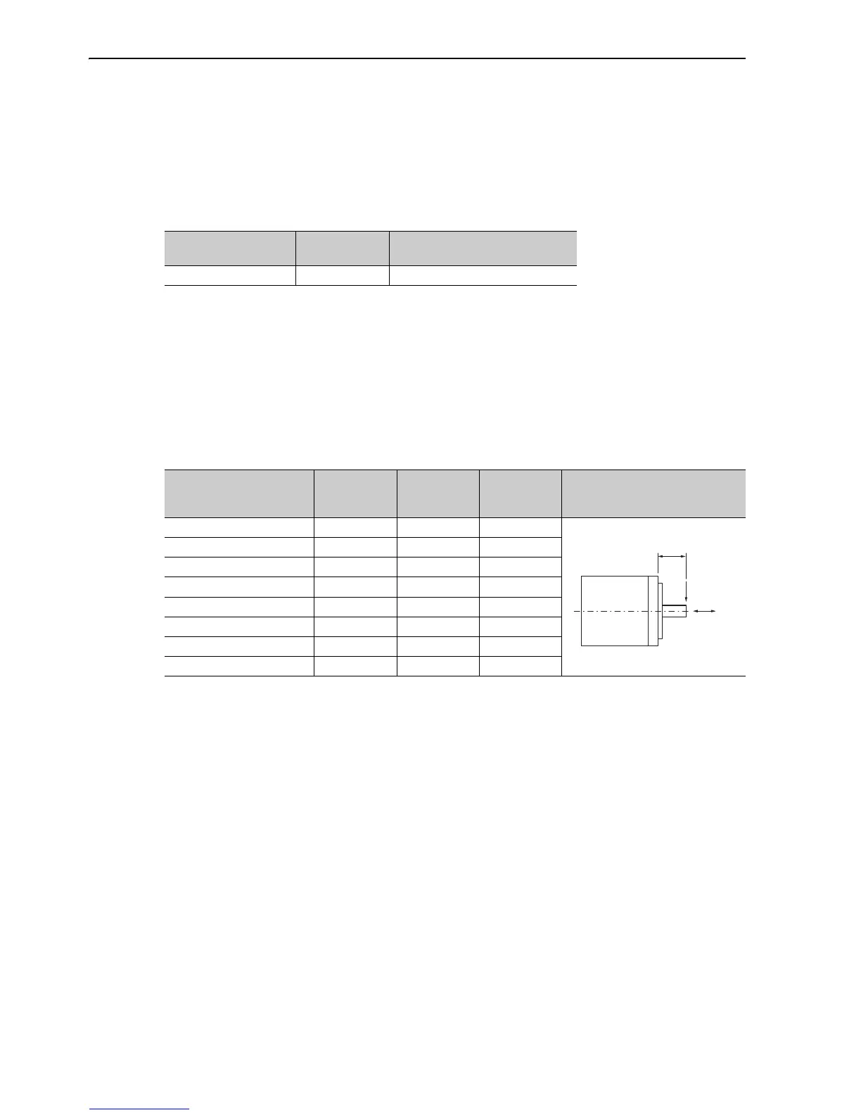
3.2.6 Allowable Radial and Thrust Loads
Design the mechanical system so thrust and radial loads applied to the servomotor shaft end during operation
fall within the ranges shown in the table.
Servomotor Model
Servomotor
Rated Output
Allowable Load Moment of Inertia
(Rotor Moment of Inertia Ratio)
SGMGV-05 to -75 0.45 to 7.5 kW 5 times
Servomotor Model
Allowable
Radial Load
Fr (N)
Allowable
Thrust Load
Fs (N)
LF
(mm)
Reference Diagram
SGMGV-05 490 98 40
SGMGV-09 490 98 58
SGMGV-13 686 343 58
SGMGV-20 980 392 58
SGMGV-30 1470 490 79
SGMGV-44 1470 490 79
SGMGV-55 1764 588 113
SGMGV-75 1764 588 113
Fr
Fs
LF
 Loading...


