3 Specifications and External Dimensions for Motors
3.1.1 Configuration
3-2
3.1 Spindle Motor
3.1.1 Configuration
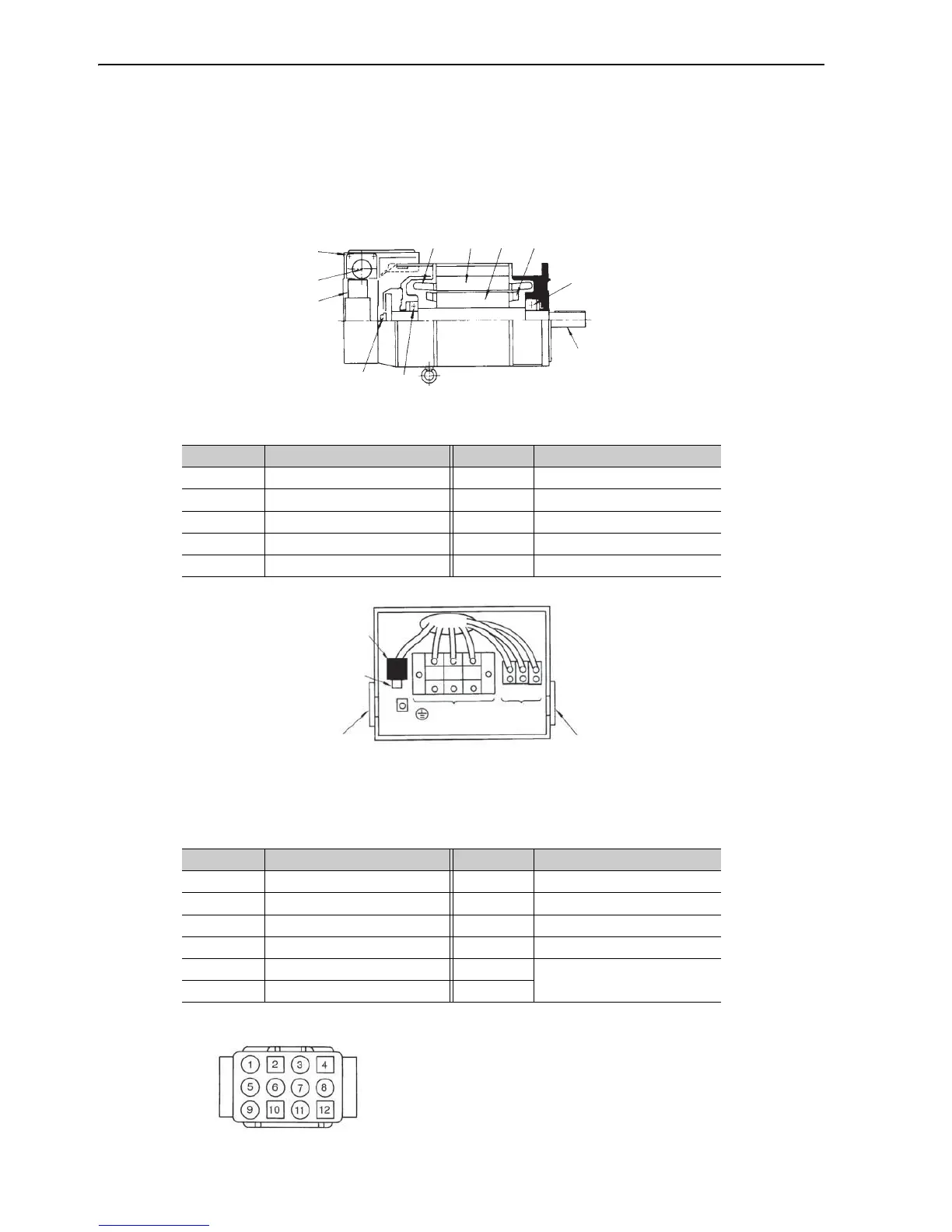
The motor configuration is shown in the following diagram.
Motor Configuration
Ter mi na l an d Co nn ec to r Ar ra ng em en t
Encoder Connector
Motor Connector
Number Name Number Name
c Output shaft h Stator winding
d Bearings i Terminal box
e Rotor j Cable socket
f Rotor short-circuit ring k Cooling fan
g Stator l Encoder
Number Ter mi na l Number Ter mi na l
1 DC+5 V 7 PC
2 0 V 8 /PC
3 PA 9 FG (Frame Ground)
4 /PA 10 SS (Shield)
5 PB 11
TS
6 /PB 12
Model: ELR-12V
Manufacturer: J.S.T.Mfg.Co.,Ltd.
Note: A crimp tool is required.
"
#
#
$
%
&
'
(
)
*
+
 Loading...


