(2) EtherCAT (CoE) Specifications
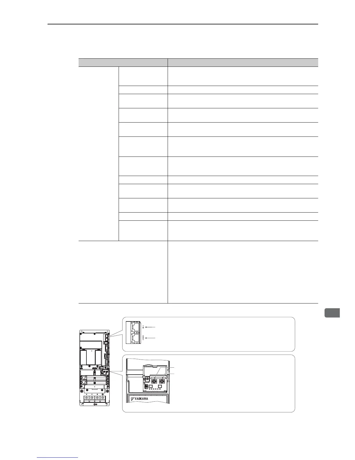
Connectors and Switches
Item Specifications
EtherCAT
Communication
Applicable
Communication
Standards
IEC 61158 Type12, IEC 61800-7 CiA402 Drive Profile
Physical Layer 100BASE-TX (IEEE802.3)
Connector
CN9A (RJ45): EtherCAT Signal IN
CN9B (RJ45): EtherCAT Signal OUT
Cable
CAT5 STP 4 pair
Note: Cables are automatically recognized by the AUTO MDIX function.
SyncManager
SM0: Mailbox output, SM1: Mailbox input
SM2: Process data outputs, SM3: Process data inputs
FMMU
FMMU0: Mapped to the process data output (RxPDO) area.
FMMU1: Mapped to the process data input (TxPDO) area.
FMMU2: Mapped to the mailbox status
EtherCAT
Commands
(Data Link Layer)
APRD, FPRD, BRD, LRD, APWR, FPWR, BWR, LWR, ARMW, FRMW
Note: APRW, FPRW, BRW, LRW Commands are not supported.
Process Data Configurations can be changed with PDO mapping.
Mailbox (CoE)
Emergency Message, SDO Request, SDO Response, SDO information
Note: TxPDO/RxPDO and Remote TxPDO/RxPDO are not supported.
Distributed Clocks
Free-run, DC mode (Can be selected.)
Supported DC cycle: 250 µs to 4 ms (every 250-µs cycle)
Slave Information IF 256 bytes (For reading only)
LED Indicator
EtherCAT Link/Activity indicator (L/A) × 2
EtherCAT RUN indicator (RUN) × 1
EtherCAT ERR indicator (ERR) × 1
CiA402 Drive Profile
•Homing mode
•Profile position mode
• Interpolated position mode
•Profile velocity mode
•Profile torque mode
•Cyclic synchronous position mode
•Cyclic synchronous velocity mode
•Cyclic synchronous torque mode
• Touch probe function
•Torque limit function
 Loading...


