No. Name Description
Analog
Output Level
Unit
Mode
Addr.
Hex
V/f
U1-11
Output
Terminal
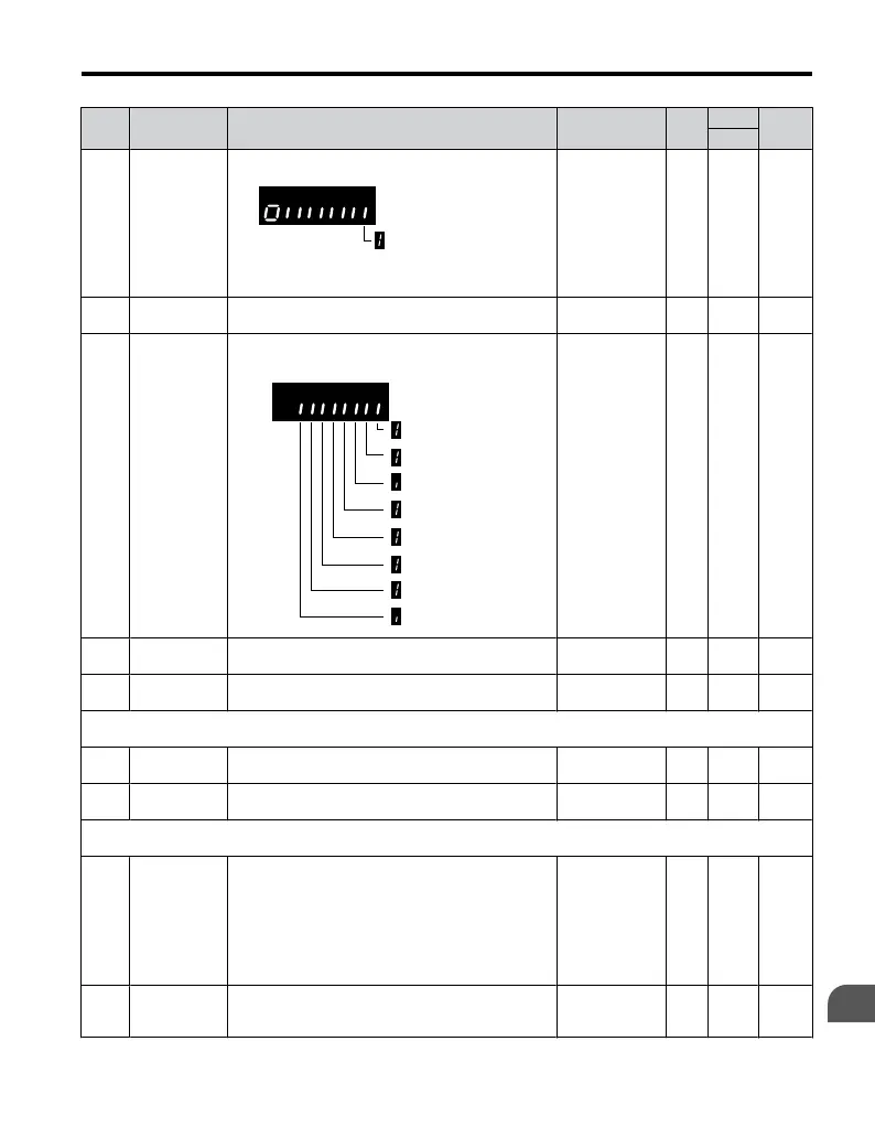
Status
Displays the output terminal status.
Multi-Function
Digital Output (fault)
(terminal MA/MB-MC)
No output signal
available
– O 4A
U1-13
Terminal Input
Level
Displays analog input A1 level: 100% when input is
10 V.
10 V: 100% 0.1% O 4E
U1-19
MEMOBUS/
Modbus Error
Code
Displays the contents of a MEMOBUS/Modbus
error.
CRC Error
Data Length Error
Not Used
Parity Error
Overrun Error
Framing Error
Timed Out
Not Used
No output signal
available
– O 66
U1-25
Software No.
(ROM)
ROM ID
No signal output
avail.
– O 4D
U1-26
Software No.
(Flash)
Flash ID
No signal output
avail.
– O 5B
U2: Fault Trace
Use U2 monitor parameters to view fault trace data.
U2-01 Current Fault Display of the current fault.
No signal output
avail.
– O 80
U2-02 Previous Fault
Display of the previous fault. o4–11 resets the values
for U2–02
No signal output
avail.
– O 81
U4: Maintenance Monitors
Use U4 parameters to display drive maintenance information.
U4-01
Accumulated
Operation
Time
Displays the cumulative operation time of the drive.
The value for the cumulative operation time counter
can be reset in parameter o4-01. Use
parameter o4-02
to determine if the operation time should start as soon
as the power is switched on or only while the run
command is present. The maximum number
displayed is 99999, after which the value is reset to
0.
No signal output
avail.
1 h O 4C
U4-04
Cooling Fan
Maintenance
Displays main cooling fan usage time in as a
percentage of their expected performance life.
Parameter o4-03 can be used to reset this monitor.
No signal output
avail.
1% O 7E
B.2 Parameter Table
YASKAWA ELECTRIC TOEP C710606 25B YASKAWA AC Drive J1000 Installation & Start-Up Manual
217
B
Parameter List
2/6/2008-14:44

 Loading...


