SA
Motor
Cooling fan
Forward run/stop
Reverse run/stop
External fault
Fault reset
0 to +10 Vdc
(2 mA)
DIP
switch S3
DC reactor
(option)
Digital inputs
(default setting)
Fault
J1000
Shield ground
terminal
Thermal relay
(option)
Braking resistor
(option)
Main circuit
Control circuit
Thermal relay for
motor cooling fan
Fault relay
1 MCCB
MC
2 MCCB
r1
s1
t1
R/L1
S/L2
T/L3
S1
S2
S3
S4
S5
<3>
<1>
<2>
-
B1+1+2 B2
R/L1
S/L2
T/L3
MC
THRX
TRX
MC
TRX
MC MA
U/T1
V/T2
W/T3
24
V
MA
MB
MC
I V
+
24 V 8 mA
M
M
r1
s1
t1
FU
FV
FW
U
V
W
SC
AM
AC
+
-
AM
+V
A1
AC
2 k
Ground
10
or less (400 V class)
100
or less (200 V class)
Setting power supply
+10.5 max. 20 mA
For single phase 200 V
power supply, use
R/L1 and S/L2.
Analog monitor
output
Digital output
250 Vac, 10 mA to 1 A
30 Vdc, 10 mA to 1 A
(default setting)
Main speed
frequency
reference.
Multi-function
programmable
Multi-step
speed 1
main/aux switch
2 MCCB
THRX
OFF
ON
MC
SA
SA
Three phase
power supply
200 to 240 V
Jumper
DIP switch S1
Sink
Source
Terminals +1, +2, , B1, and B2
are for connecting options.
Never connect power supply
lines to these terminals.
_
Monitor
output
Option unit
connector
main circuit terminal
shielded line
twisted-pair shielded line
control terminal
<4>
<5>
<6>
<7>
0 to +10 V (20 k )
(0)4 to 20 mA (250 )
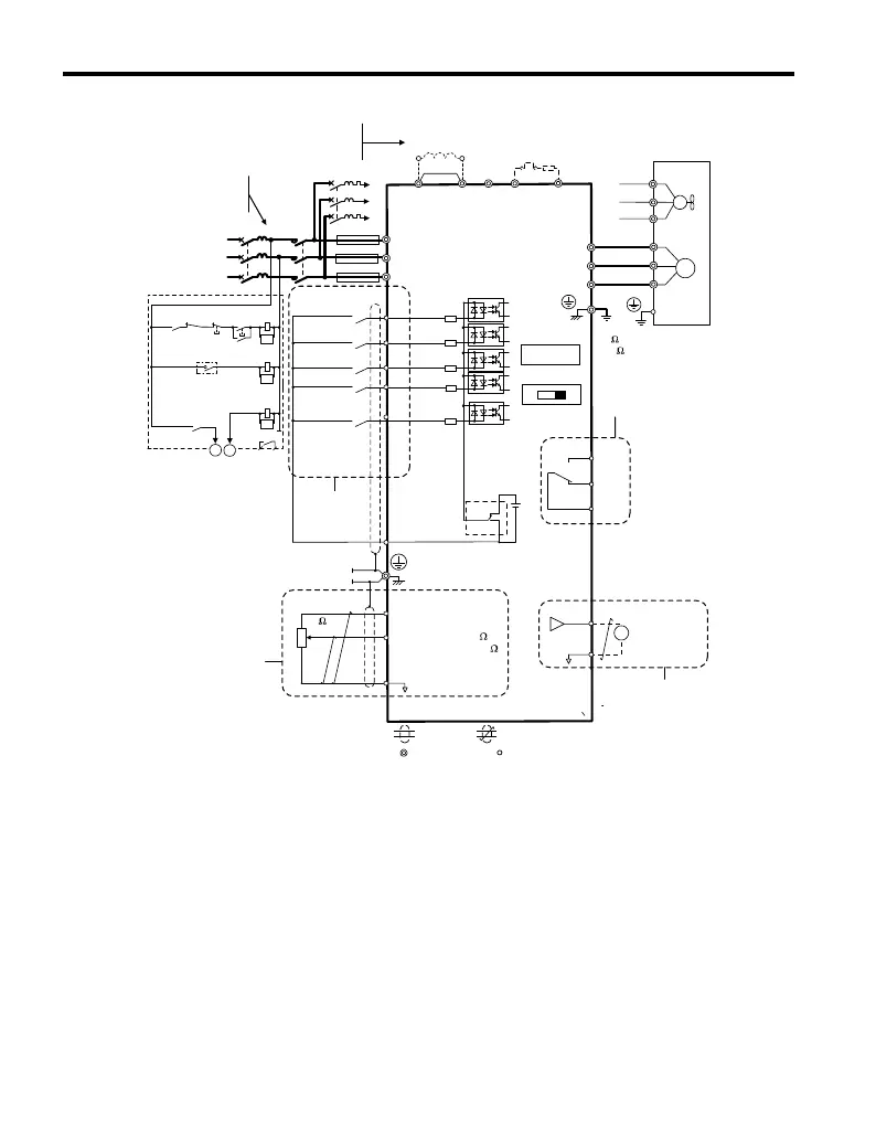
Figure 3.1 Drive Standard Connection Diagram (200 V Class Example)
<1> Remove the jumper when installing an optional DC reactor.
<2> The MC on the input side of the main circuit should open when the thermal relay is
triggered.
<3> Self-cooled motors do not require separate cooling fan motor wiring.
<4> Connected using sequence
input signal (S1 to S5) from NPN transistor; Default: sink
mode (0 V com).
<5> Use only a +24 V internal power supply in sinking mode; the source mode requires
an external power supply Refer to I/O Connections on page 60.
<6> Minimum load: 5 Vdc, 10 mA (reference value).
3.2 Standard Connection Diagram
44
YASKAWA ELECTRIC TOEP C710606 25B YASKAWA AC Drive J1000 Installation & Start-Up Manual
2/6/2008-14:44

 Loading...


