n
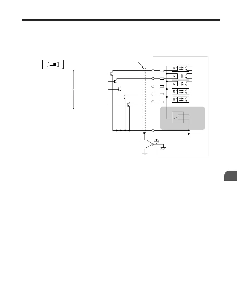
Transistor Input Signal Using 0 V Common/Sink Mode
When controlling the digital inputs by NPN transistors (0 V common/sinking mode), set the
DIP switch S3 to SINK and use the internal 24 V power supply.
S1
SINK
SOURCE
S2
S3
S3
+24 V
S4
S5
SC
SINK
SOURCE
FWD Run/Stop
REV Run/Stop
External Fault N.O.
Fault Reset
Multi-step Speed 1
Shielded Cable
Multi-funciton input
Figure 3.17 Sinking Mode: Sequence from NPN Transistor (0 V Common)
3.8 I/O Connections
YASKAWA ELECTRIC TOEP C710606 25B YASKAWA AC Drive J1000 Installation & Start-Up Manual
61
3
Electrical Installation
2/6/2008-14:44

 Loading...


