Power
supply
Thermal
relay
Motor
Drive
Braking resistor
Thermal relay switch for
external braking resistor
Fault contact
MC
SA
SA
SA
MCON
MC
OFFTHRX
THRX
TRX
MC
TRX
MA MC
R/L1
B1 B2
S/L2
T/L3
U/T1
V/T2
W/T3
MCCB
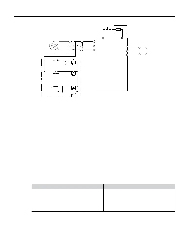
Figure 3.20 Connecting a Braking Resistor
4.
Follow manufacturer instructions to connect the resistor unit to the drive using proper
wire gauge according to local electrical codes.
Power leads for the remote mount resistors generate high levels of electrical noise;
group these signal leads separately.
5.
Mount the resistor unit on a noncombustible surface. Maintain minimum side and top
clearances according to resistor manufacturer instructions.
WARNING! Fire Hazard. Do not use improper combustible materials. Failure to comply could
result in death or serious injury by fire. Attach the drive or braking resistors to metal or other
noncombustible material.
6.
Reinstall drive covers and resistor covers, if provided.
7.
Set parameter L3-04 = “0” to disable stall prevention during deceleration.
Set parameter L8-01 to “1” to enable overheat protection when using Yaskawa
heatsink-mounted braking resistor.
Set L8-01 = “0” for other braking resistor types.
Table 3.14 Braking Resistor Settings
Parameter Settings
L8-01: Internal Dynamic Braking Resistor
Protection Selection
0: Disabled. The drive will not provide overheat
protection. Supply separate means of overheat
protection.
1: Enabled. Braking Resistor is protected from
overheat.
L3-04: Stall Prevention During Deceleration 0: Stall prevention disabled.
8.
Operate the system and verify the required deceleration rate is obtained during
dynamic braking or stopping.
3.10 Braking Resistor
66
YASKAWA ELECTRIC TOEP C710606 25B YASKAWA AC Drive J1000 Installation & Start-Up Manual
2/6/2008-14:44

 Loading...


