Basic Programming 5 - 9
In some situations there is no setpoint but rather two feedback inputs. The drive can be programmed to maintain a set
differential between two analog signals. If input A2 is configured as a “PI Differential” (H3-09=16), then the Drive will
attempt to maintain a set difference between the measurements read on inputs A1 and A2. This set difference is programmed
by the PI Offset parameter (b5-07).
b5-01 PI Mode
The Drive can be used as a stand-alone PI controller. If PI functionality is selected by parameter b5-01, the Drive will adjust
its output to cause the feedback from a transducer match the PI setpoint (b5-19). The setting of b5-01 will determine whether
PI functionality is disabled (b5-01=0), enabled (b5-01=1), or enable with the output of the PI function used to trim the Speed
Command (b5-01=2).
b5-02 Proportional Gain Setting
The proportional gain will apply a straight multiplier to the calculated difference between the PI Setpoint (b5-19) and the
measured transducer feedback.
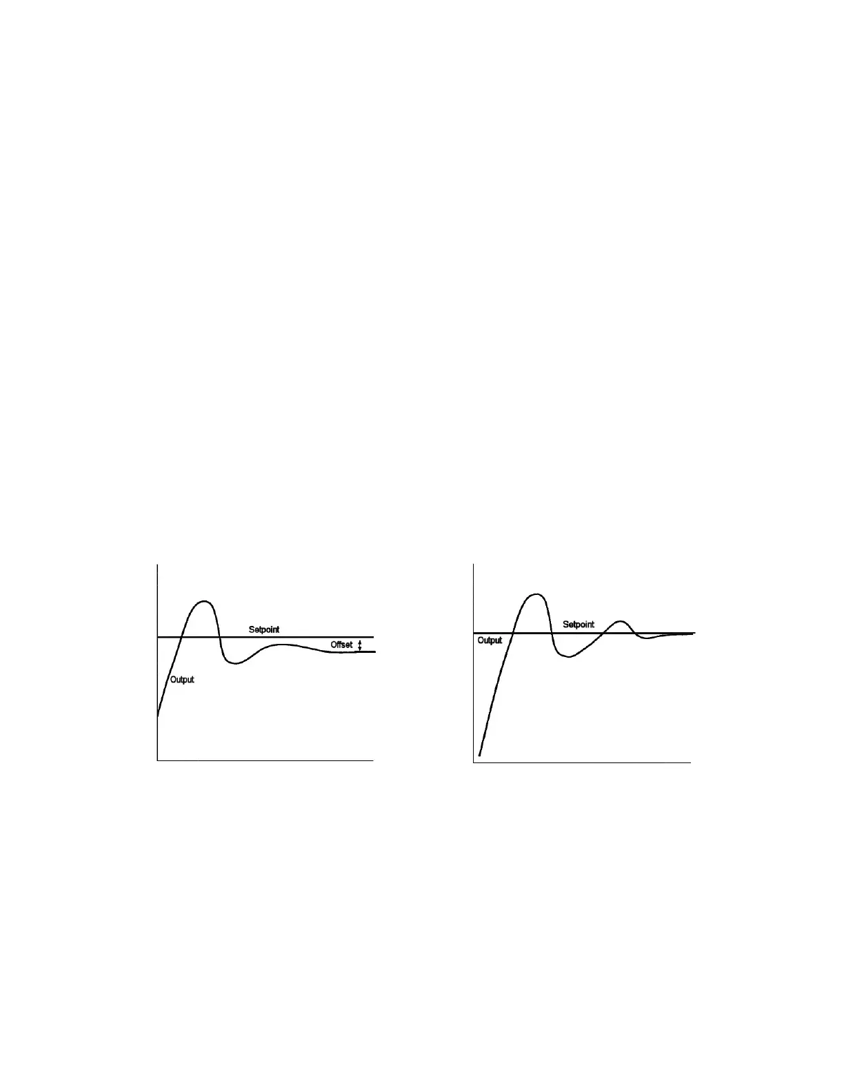
b5-03 Integral Time Setting
The Integral factor of PI functionality is a time-based gain that can be used to eliminate the offset (difference between the
setpoint and feedback at steady state). The smaller the Integral Time set into b5-03, the more aggressive the Integral factor
will be. To turn off the Integral Time, set b5-02=0.00.
Fig 5.9 PI Response With and Without Intregal Factor
b5-04 Integral Limit Setting
On some applications, especially those with rapidly varying loads, the output of the PI function may have large oscillations. To
suppress these oscillations, a limit can be applied to the intregal factor by programming b5-04.
b5-06 PI Output Limit
Places a cap on the output of the PI function. Limiting the PI function may help to prevent large overshoots in the Drive’s
response to error (the difference between the setpoint and the feedback).