5.12 Holding Brake
5.12.1 Brake Operating Sequence
5
Basic Functions That Require Setting before Operation
5-33
Linear Servomotors: The brake delay times depend on the brake that you use. Set the parameters related to
/BK signal output timing according to the delay times for the brake that you will actually use.
*2. Before you output a reference from the host controller to the SERVOPACK, wait for at least 50 ms plus the
brake release delay time after you send the SV_ON command.
*3. Use the following parameters to set the timing of when the brake will operate and when the servo will be turned
OFF.
• Rotary Servomotors: Pn506 (Brake Reference-Servo OFF Delay Time), Pn507 (Brake Reference Output
Speed Level), and Pn508 (Servo OFF-Brake Command Waiting Time)
• Linear Servomotors: Pn506 (Brake Reference-Servo OFF Delay Time), Pn508 (Servo OFF-Brake Command
Waiting Time), and Pn583 (Brake Reference Output Speed Level)
Connection Examples
Refer to the following section for information on brake wiring.
4.4.4 Wiring the SERVOPACK to the Holding Brake on page 4-33
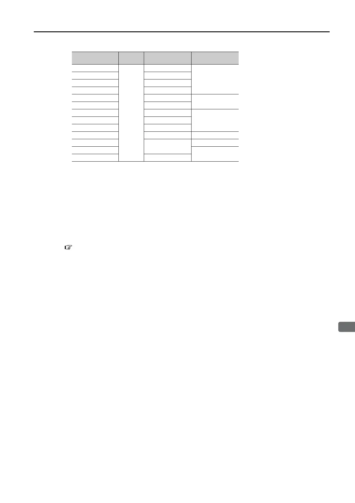
Model Voltage
Brake Release
Delay Time [ms]
Brake Operation
Delay Time [ms]
SGM7J-A5 to -04
24 VDC
60
100
SGM7J-06 and -08 80
SGM7A-A5 to -04 60
SGM7A-06 to -10 80
SGM7A-15 to -25 170
80
SGM7A-30 to -50 100
SGM7P-01 20
100SGM7P-02 and -04 40
SGM7P-08 and -15 20
SGM7G-03 to -20 100 80
SGM7G-30 to -44
170
100
SGM7G-55 to -1A
80
SGM7G-1E 250

 Loading...


