12.4 Monitoring Communications Data during Alarms or Warnings
12-58
12.4
Monitoring Communications Data during Alarms or Warnings
You can monitor the command data that is received when an alarm or warning occurs, such as
a data setting warning (A.94) or a command warning (A.95) by using the following parame-
ters. The following is an example of the data when an alarm or warning has occurred in the nor-
mal state.
Command Data during Alarms and Warnings: Pn890 to Pn8A6
Response Data during Alarms and Warnings: Pn8A8 to Pn8BE
Note: 1. Data is stored in little endian byte order and displayed in the hexadecimal.
2. Refer to the following manual for command details.
Σ-7-Series MECHATROLINK-III Communications Standard Servo Profile Command Manual (Manual No.:
SIEP S800001 31)
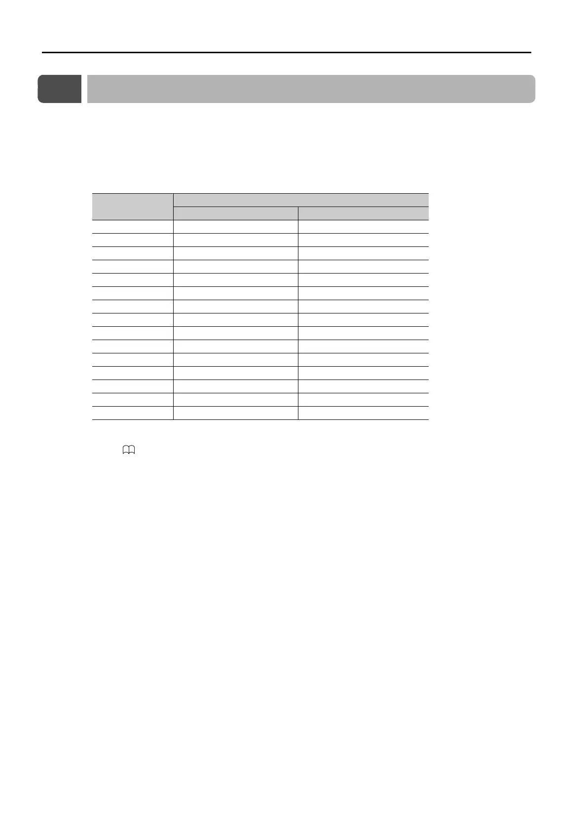
Command Byte
Sequence
Command Data Storage When an Alarm or Warning Occurs
CMD RSP
0 Pn890 = n.XX Pn8A8 = n.XX
1 Pn890 = n.XX Pn8A8 = n.XX
2 Pn890 = n.XX Pn8A8 = n.XX
3 Pn890 = n.XX Pn8A8 = n.XX
4 to 7 Pn892 Pn8AA
8 to 11 Pn894 Pn8AC
12 to 15 Pn896 Pn8AE
16 to 19 Pn898 Pn8B0
20 to 23 Pn89A Pn8B2
24 to 27 Pn89C Pn8B4
28 to 31 Pn89E Pn8B6
32 to 35 Pn8A0 Pn8B8
36 to 39 Pn8A2 Pn8BA
40 to 43 Pn8A4 Pn8BC
44 to 47 Pn8A6 Pn8BE

 Loading...


