5-84
Note 1. The following errors are not included in the error trace: CPF00, 01, 02, 03, UV1, and UV2.
2. If the PUF fault is already indicated in U2- or U3-, even if the PUF fault is detected again, the fault trace is not updated.
* The minimum unit differs depending on the Inverter capacity. (0.01 A for Inverter of 0.4 kW to 7.5 kW, and 0.1 A for Inverter of 11 kW or more)
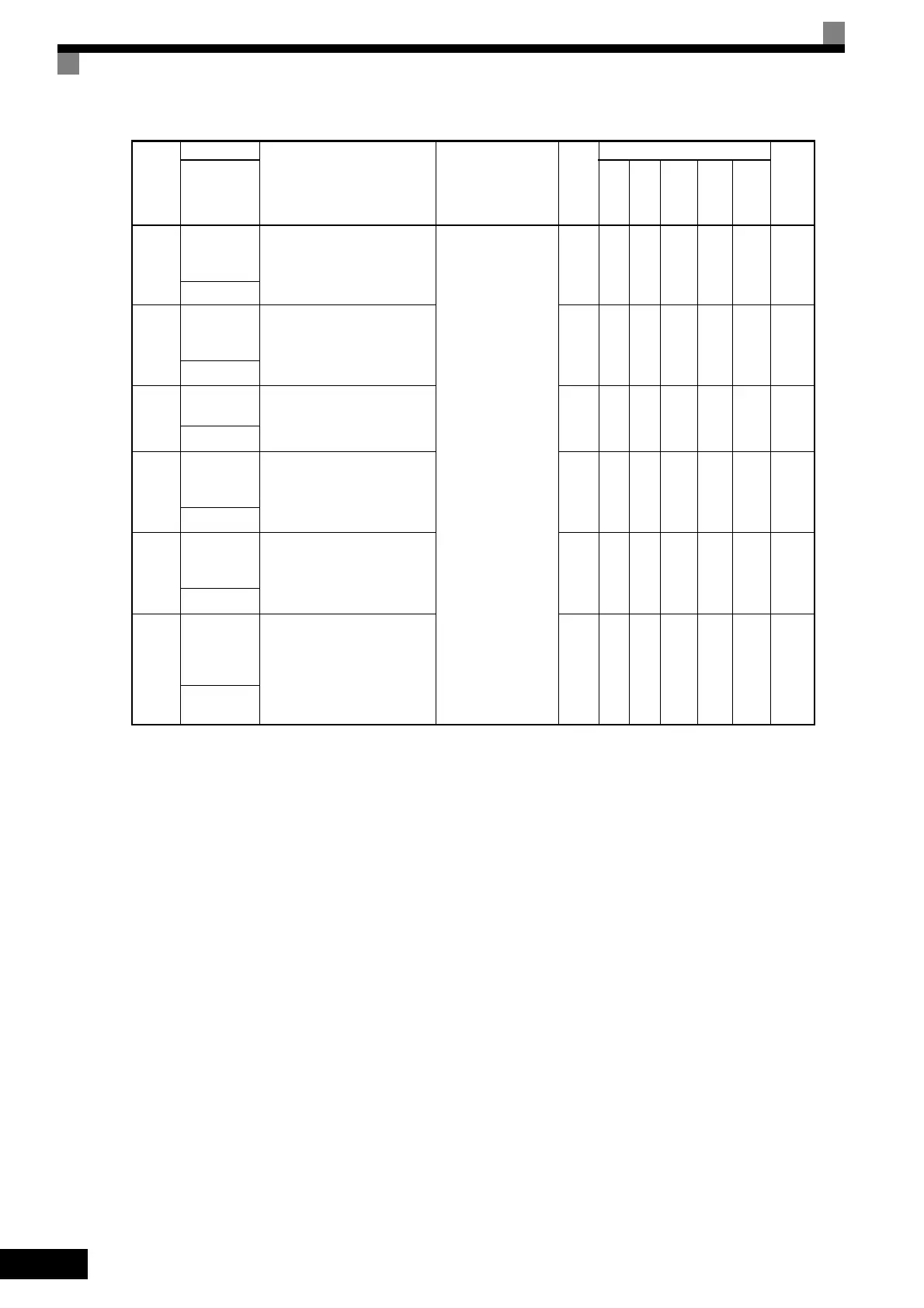
U2-11
Input termi-
nal status at
fault
The input terminal status when
the previous fault occurred.
The format is the same as for U1-
10.
(Cannot be output.)
-AAAAA8AH
输入端子状态
U2-12
Output termi-
nal status at
fault
The output terminal status when
the previous fault occurred. The
format is the same as for U1-11.
-AAAAA8BH
输出端子状态
U2-13
Operation
status at fault
The operating status when the
previous fault occurred. The for-
mat is the same as for U1-12.
-AAAAA8CH
运行状态
U2-14
Cumulative
operation
time at fault
The operating time when the pre-
vious fault occurred.
1
hr
AA A A A 8DH
累积时间
U2-21
Peak hold
current at
fault
Displays the peak hold current
when the last fault occurred.
0.01
A
*
AA A A A7E6H
峰值保持电流
U2-22
Peak hold
output
frequency at
fault
Displays the frequency value at
the moment the current reached
its peak value when the last fault
occurred.
0.01
Hz
AA A A A7E7H
峰值保持输出
频率
Con-
stant
Number
Name
Description
Output Signal
Level During
Multi-Function
Analog Output
Min.
Unit
Control Methods
MEMO-
BUS
Regis-
ter
Display
V/f
V/f
with
PG
Open
Loop
Vec-
tor
1
Flux
Vec-
tor
Open
Loop
Vec-
tor
2
 Loading...


