6-18
IM DL850E-03EN
Item Specifications
Safety standard Compliant standards
2
EN61010-1, EN61010-2-030, EN61010-031, EN 60825-1
• Overvoltage category (installation category) II
3
• Measurement Category: See the specifications of each module.
4
• Pollution degree 2
5
Approved (DL850E, DL850EV, 701250, 701251, 701255, 701267, 701261, 701262, 701265,
701270, 701271, 701275, 701281, 720210, 720211, 720220, 720221, 720230, 720240, 720241,
720243, 720254, 700986, 700987, 701953, 701955, 701956, 701957, 701958, 702911, 702912)
• Bridgehead for the strain module
Use the 701955 or 701956 with the 701270, and use the 701957 or 701958 with the 701271.
Emissions Compliant standards
EN61326-1 Class A, EN61326-2-1, EN 55011 Class A, Group 1, EMC Regulatory Arrangement
in Australia and New Zealand EN 55011 Class A, Group 1, Korea Electromagnetic Conformity
Standard ( 한국 전자파적합성기준 )
Approved (DL850E, DL850EV, 701250, 701251, 701255, 701267, 701261, 701262, 701265,
701270, 701271, 701275, 701281, 720210, 720211, 720220, 720221, 720230, 720240, 720241,
720243, 720254, 700986, 700987, 701953, 701955, 701956, 701957, 701958, 702911, 702912)
EN61000-3-2, EN61000-3-3
This product is a Class A (for industrial environments) product. Operation of this product in a
residential area may cause radio interference in which case the user is required to correct the
interference.
Test items
1. Power supply terminal noise
2. Radiation emission
3. Power supply harmonic regulation
4. Power supply voltage fluctuation and flicker
Cable conditions (DL850E/DL850EV)
Current probe
When connecting a current probe to the input terminal and probe power terminal of a module,
attach a single ferrite core
6
to both cables on the side of the cables closest to the DL850E/
DL850EV.
GP-IB cable
Use a shielded cable that is 3 m or less in length.
USB cable
Use a shielded cable that is 3 m or less in length, and attach a ferrite core
6
to the side of the
cable closest to the DL850E/DL850EV.
Ethernet cable
Use a shielded cable that is 30 m or less in length, and attach a ferrite core
6
to the side of the
cable closest to the DL850E/DL850EV.
External clock input, external trigger input, external trigger output
Use a shielded cable that is 3 m or less in length, and attach a ferrite core
6
to the side of the
cable closest to the DL850E/DL850EV.
IRIG cable
Use a shielded cable that is 3 m or less in length, and attach a ferrite core
6
to the side of the
cable closest to the DL850E/DL850EV.
External HDD cable
Use a shielded cable that is 3 m or less in length.
Video signal output cable
Use a shielded cable that is 3 m or less in length, and attach a ferrite core
7
to the side of the
cable closest to the DL850E/DL850EV.
External I/O cable
Use a shielded cable that is 3 m or less in length, and attach a ferrite core
6
to the side of the
cable closest to the DL850E/DL850EV.
DC power cable
Attach a ferrite core
7
to the DC power cable.
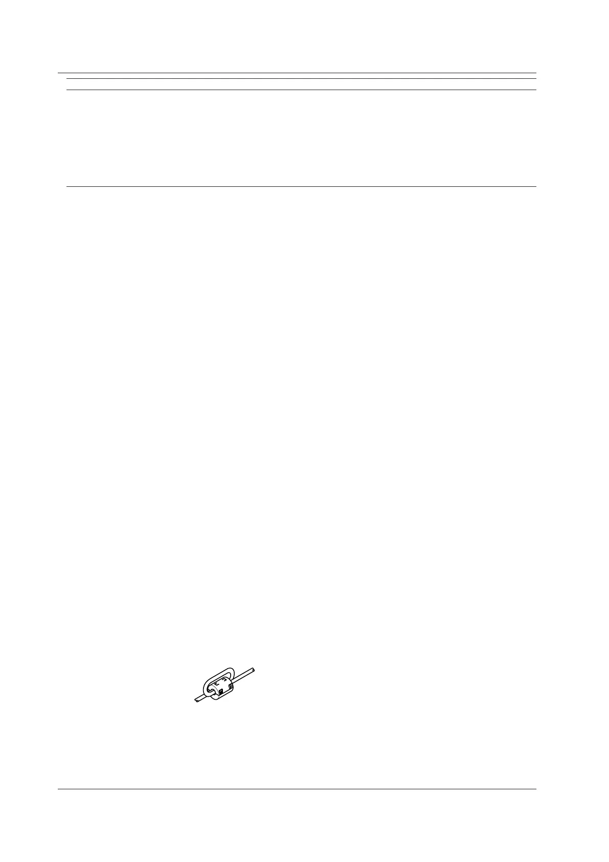
Probe power cable
Use the dedicated cable, and attach a ferrite-core
6
to the side of the cable closest to the
DL850E/DL850EV by passing the cable twice through the core.
Example of passing the cable through twice
Cable conditions (input module)
50 Ω terminator 700976 (for the 701281, 720211, 720243, and 720254)
Isolated probe 700929 (for the 701250, 701251, 701255, 701275, and 720210)
Attach a ferrite-core
6
to the side of the cable closest to the DL850E/DL850EV by passing the
cable twice through the core.
Twisted pair cable for the 701261, 701262, and 701265
Use a cable that is 3 m or less in length, and attach a ferrite-core
6
to the side of the cable
closest to the DL850E/DL850EV by passing the cable twice through the core.
6.12 General Specifications

 Loading...


