<9. Advanced Engineering >
● Execution Order between Sets of Line-Connected POUs
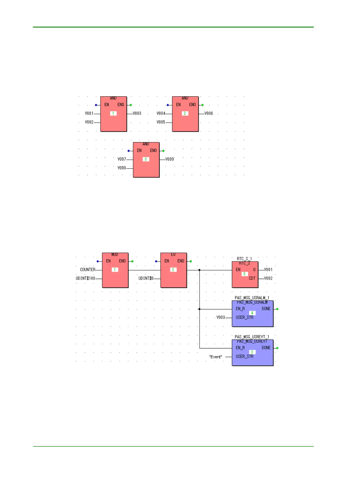
Within a code worksheet coded in FBD or LD, sets of POUs connected by lines
(circuit units) are executed from top to bottom, and from left to right. In the following
example, the two POUs at the same height on top are executed from left to right,
followed by the POU at the bottom.
● Execution Order within a Set of Line-Connected POUs
Within a set of POUs connected by lines (that is, within a circuit unit), the execution
order of flow branches cannot be specified by a user. To control the execution order,
split the circuit.
In the single circuit example shown below, POUs indicated with execution order
numbers 3 to 5 are not executed from top to bottom.
When the circuit is split into three pieces, the POUs indicated with execution order
numbers 3 to 5 are now executed from top to bottom, as described in the case
“Execution Order between Sets of Line-Connected POUs.”
 Loading...


