OPERATION
Cell Observer SD Switching the System on Carl Zeiss
M60-2-0021 e 01/2009 423638-7044-001 53
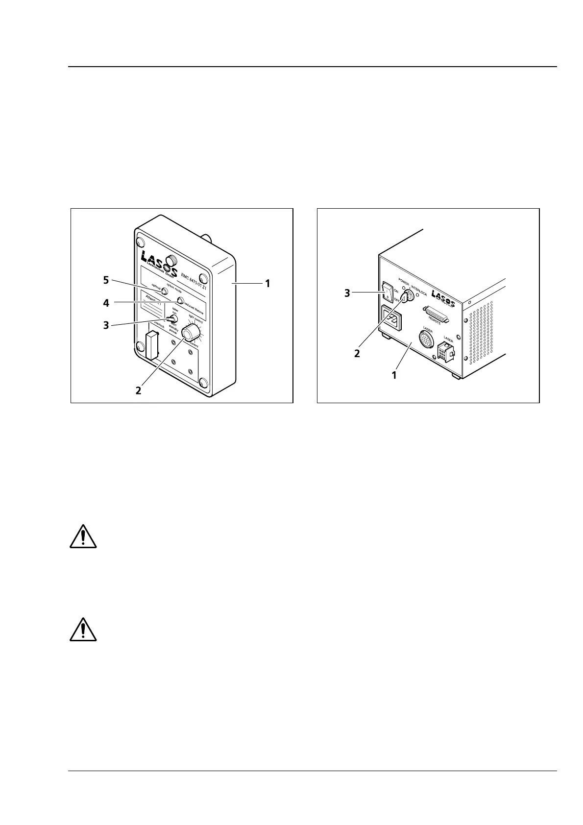
4.2.2 Turning the Multiline Argon Laser On
• Make sure that the toggle switch (
Fig. 4-5/3) at the laser power pack control module (Fig. 4-5/1) is in
Standby position (down) and the power controller (
Fig. 4-5/2) in left stop position before you turn the
laser on.
• Transfer the On/Off switch at the power pack into position I (
Fig. 4-6/3). Power is supplied to the
argon laser.
• Turn the key switch at the power pack into position I (
Fig. 4-6/2) to trigger the argon laser.
1 Casing
2 Potentiometer for power control
3 Standby switch
4 Green LED optimal (lights when laser energy within
nominal range)
5 Red LED reduced life time (lights when laser energy
too high)
Fig. 4-5 Control unit of multiline argon laser
1 Power supply unit of 100 mW laser
2 Key switch
3 On/Off switch
Fig. 4-6 Power supply unit of multiline argon
laser
Nominal laser power will be available within a few seconds. Operation at nominal power and
the specified laser lifetime can only be warranted if the power selection potentiometer
(
Fig. 4-5/2) is in a position approximately 12 hours. The green LED (Fig. 4-5/4) will light in this
case. For operation at a lower power setting, the potentiometer can be rotated anticlockwise. If
operated with a power setting above nominal level (potentiometer in a position greater than 12
hours), the laser’s lifetime will be reduced. The red LED will light (
Fig. 4-5/5).
If the safety device is found to function in a non-conforming manner, you should shut the
system down, clearly mark it as defective and contact the Service Department of Carl Zeiss
MicroImaging GmbH immediately.