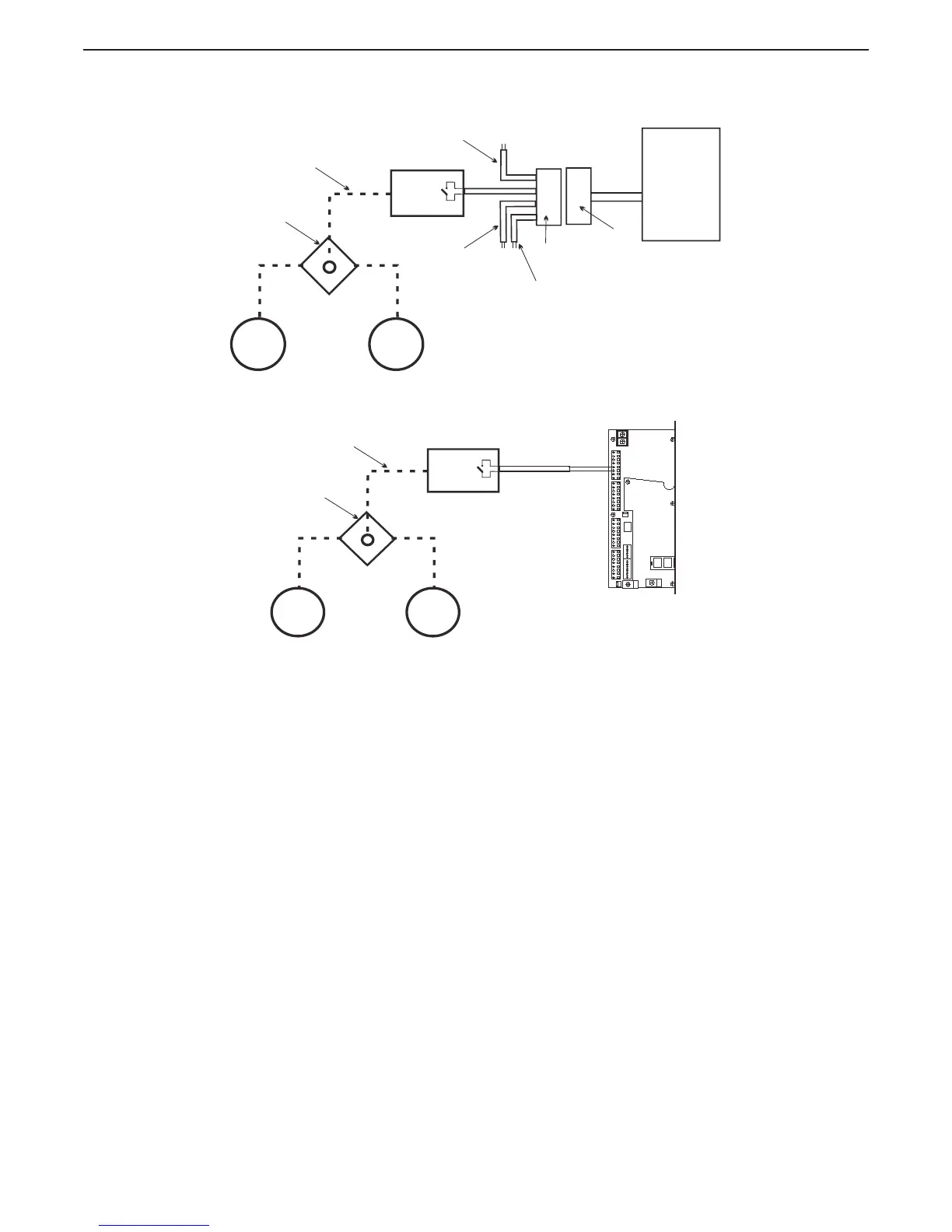
Figure 8-3: Clutch Pressure Switch with Processor Harness Diagram
Figure 8-4: Clutch Pressure Switch with Processor Hard-Wired Diagram
The installation of the Clutch Pressure Switch is the same for both methods of operation. (Refer to
Figure 8-3: Clutch Pressure Switch with Processor Harness Diagram or Figure 8-4: Clutch Pressure
Switch with Processor Hard-Wired Diagram)
A Install a Shuttle Valve on or near the Transmission.
B Connect hydraulic line from the Ahead and Astern Clutches.
C Connect a hydraulic line that is no longer than 5 feet (1,524m)and at approximately the same
height between the Shuttle Valve and the Pressure Switch.
D Connect the Power Wire Harness’s Clutch Pressure Interlock cable to the Pressure Switch’s
normally open contact.
E Calibrate the Pressure Switch to close when adequate Clutch Pressure is reached. (Refer to
the Transmission manufactures Installation Manual)
Processor
Power
Pigtail
Power Wire
Harness
To Starter Solenoid
To External Status Indication Circuit
Pressure
Switch
Hydraulic
Line
Shuttle Valve
Astern
Clutch
Pack
Ahead
Clutch
Pack
To Processor
DC Power
Source
15319.1_ART
Processor
Pressure
Switch
Hydraulic
Line
Shuttle Valve
Astern
Clutch
Pack
Ahead
Clutch
Pack
15319.2_ART
SERIAL
OPI ALARM
STATION5
START
INTERLOCK
ELEC-THR
STATION3
CLUTCH
STATION1
JMP1
DS2
DS1
P1
TB7
TB8
TB5
TB3
TB6
PB2
TB1
2 3 5 6 8
4
7 9 10
1
1
3 4
6 7
2 5
7 6 4 3
8
5
2
1
7
6 4 3
8
5
2
1
7 6 4 3
1
8
5
2
1
2
7 6
4 3 1
8
5
2
J1
P2
Green
-
(Clutch Pressure )
Blue
+
(Clutch Pressure )

 Loading...