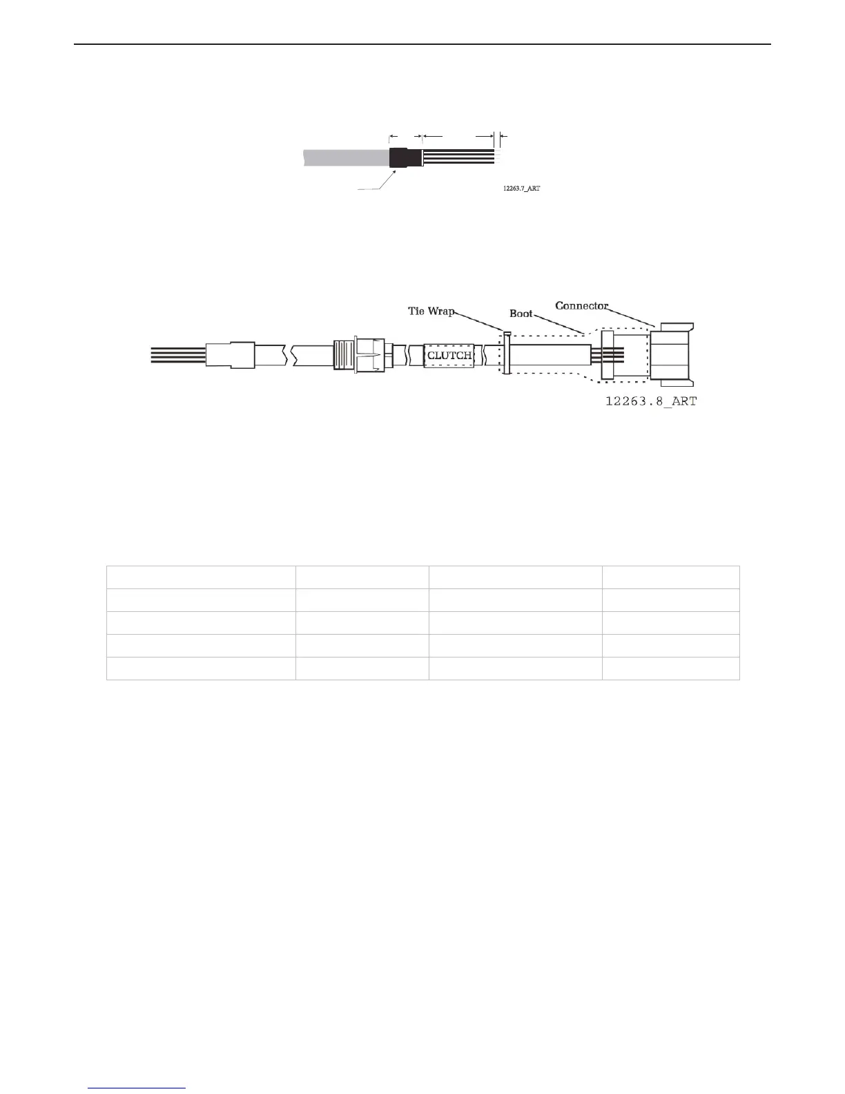
D Slide a 1 inch (24,5mm) piece of heat shrink over the end of the cable as
shown in Figure 4-20: Clutch Cable Heat Shrink in Processor.
Figure 4-24: Clutch Cable Heat Shrink in Processor
E Strip back 3/8 inch (9,53mm) from the four conductors and connect to the
Processor as shown in Table 4-5: Clutch Termination Table.
4.4.7.1.2 Plug Termination
A Strip back 2 1/4 inches (57,15mm) of PVC jacketing.
Figure 4-25: Clutch Cable Plug Termination Connections
B Slide the boot onto the cable.
C Strip back 1/4 inch (6,35mm) from the four conductors.
D Crimp Pins onto the eight conductors.
E Insert the pins into the appropriate terminations as shown in Table 4-5: Clutch
Termination Table.
F Slide the boot over the connector.
G Tie-wrap the boot in place.
4.4.8 Location 12 Installation
4.4.8.1 Throttle Cable (Location 12)
A 2-conductor shielded cable is required when hard-wiring the engine to the Processor.
A Install a 1/2 inch Liquid Tight Connector into hole no.12 of the Processor.
B Run the throttle cable through the connector so that 4 inches (101,6mm) of the cable is
pulled through.
C Tighten the Liquid Tight Connector nut.
D Strip back the PVC jacket to within 1/2 inch (12,7mm) of the enclosure.
E Clip the shield wire to 3/4 inch (19,1mm) of length.
Table 4-7: Clutch Termination Table
Description Conductor Color Processor Termination Plug Termination
Ahead Clutch Solenoid (+) Brown TB11-2 Pin 3
Ahead Clutch Solenoid (-) Green TB11-6 Pin 4
Astern Clutch Solenoid (+) Black TB11-1 Pin 5
Astern Clutch Solenoid (-) Yellow TB11-5 Pin 6
12263.7_ART
Heat Shrink
1 inch
(25,4mm)
4 inches
(101,6mm)
3/8 inch
(9,53mm)

 Loading...