4.6 Push-Pull Cable Connections
4.6.1 Processor
A Remove the #10-32 jam nut and the two rubber seals from the end of each push-pull cable
that is to connect to the Processor(s) only; discard the seals, but save the nuts.
B Remove one screw from each Cable Anchor Clip and loosen the other screw. Swing the two
Clips clear. Refer to Figure 4-27: Processor Cable Clamp Rotation.
Figure 4-27: Processor Cable Clamp Rotation
C Insert the appropriate push-pull cable into the Processor according to the labels located
above the cable clips on the Processor enclosure.
D When the push-pull cable end is visible within the Processor interior, reinstall the #10-32 jam
nut.
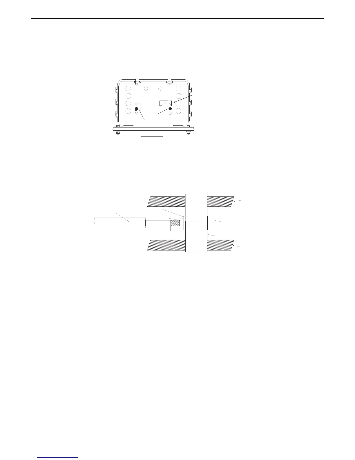
E Connect the push-pull cables to the hex nuts (See Figure 4-28: Push-Pull Cable Interior
Connection). Use a 7/16 inch socket to turn the hex nut onto the cable rod end until there is
approximately 5/16 inch (7,9mm) of thread showing beyond the jam nut.
Figure 4-28: Push-Pull Cable Interior Connection
F Use a 7/16 inch socket wrench and a 5/16-inch open end wrench to tighten the jam nuts.
G Position the Cable Anchor Clips to secure the cables to the Processor housing.
H Install the screws removed in step B).
I Tighten all Cable Anchor Clip screws.
Rotate Cable Clamp out of
the way, prior to inserting
the push-pull cable.
Front View
0658_ART
Servo 1
Servo 2
Push-Pull Cable
Jam Nut
Snap Ring
Lead Screw
Lead Screw
Cross-bar
5/16 inch
(7,9mm)
7/16 inch (11,11mm)
Hex Nut
12280_ART